Low Power Tinyml Predictive Maintenance For Solenoid Valve Sticking In High Cycle Factories
An advanced TinyML system for predictive maintenance using industrial sensor data and machine learning-based anomaly detection. Designed for resource-constrained embedded devices while maintaining high accuracy for fault detection in industrial IoT applications.
A TinyML model using Arduino Portenta and Edge Impulse to predict the anomalous operation in Industrial machineries like Pump, valves & fans
When computers were introduced in Industry 3.0, it was disruptive thanks to the addition of an entirely new technology. Now, and into the future as Industry 4.0 unfolds, computers are connected and communicate with one another to ultimately make decisions without human involvement. A combination of cyber-physical systems, the Internet of Things and the Internet of Systems make Industry 4.0 possible and the smart factory a reality. As a result of the support of smart machines that keep getting smarter as they get access to more data, our factories will become more efficient and productive and less wasteful. Ultimately, it's the network of these machines that are digitally connected with one another and create and share information that results in the true power of Industry 4.0.
Predictive maintenance uses an analytical approach; utilizing real-time and historical data to highlight where a machine is not performing as it should so that it can be repaired ahead of time.
I have created a Prototype using Arduino Portenta H7 and Edge Impulse for predictive maintenance application.
For Industrial machineries audio datasets, I have used open source datasets from the below link,
https://dcase.community/documents/workshop2019/proceedings/DCASE2019Workshop_Purohit_21.pdf
This dataset is made available by Hitachi, Ltd. under a Creative Commons Attribution-ShareAlike 4.0 International (CC BY-SA 4.0) license.
The dataset was collected using a TAMAGO-03 microphone manufactured by System In Frontier Inc. It is a circular microphone array that consists of eight distinct microphones.
The microphone array was kept at a distance of 50 cm from the machine (10 cm in the case of valves), and 10-second sound segments were recorded.
In Each machineries, there will 7 different models datasets are recorded. In the below table, Valve 00 denotes model 1 and valve 06 denotes model 7. Each model will vary in dimensions, speed and mechanical configurations. Same approach applicable for fan and pump.
In upcoming steps, I have mentioned the steps for One Edge Impulse model - Fan in this project. The same approach applicable for Another two models.I also shared the link of other two models.
In Edge Impulse, Once datasets are downloaded. You can go to the uploader option in Edge Impulse and upload the audio samples with label "abnormal" and "normal".
Then go to Create Impulse section, and select Windows size 2000ms and windows increase as 1000ms. I have selected spectrogram.
In neural network configuration, I have 1D convolution and followed Dense neural network. The training cycle is 100 with learning rate as 0.005.
In testing data, Model achieved 96.33 % accuracy. It indicates, the model performs with good accuracy in datasets.
Once the testing is done, then go to "Deployment" option and select "build firmware" -> Arduino Portenta H7 for build. I have chosen Quantized (int8). In edge Impulse, they have used EON compiler for achieving this resource reduction with higher accuracy and less latency.
Press the reset button in Portenta H7 twice to set it to "flash mode" and then open.bat (windows) or. command (mac users) for flashing the firmware.
Once the flash is completed. Then open the new "terminal window" and run the below command to start the inference.
arXivLabs is a framework that allows collaborators to develop and share new arXiv features directly on our website.
Have an idea for a project that will add value for arXiv's community? Learn more about arXivLabs .
Hardware Schematics & Pinout Diagrams
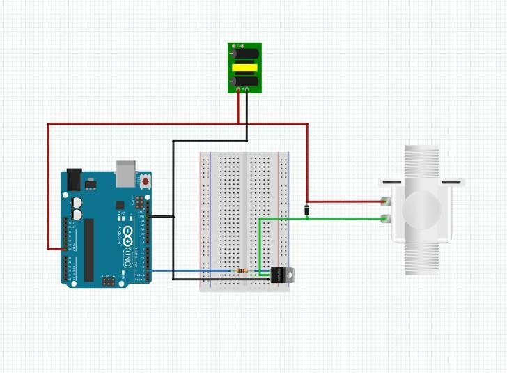
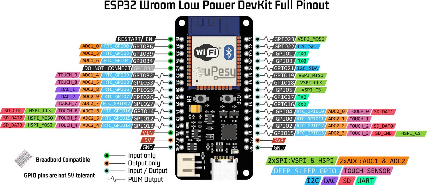
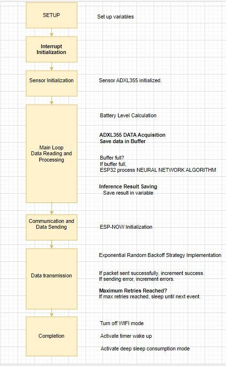
Hardware Signal & Control Flow Architecture
(9V DC / USB 5V)
(ADC Acquisition)
(Filtering / State Machine)
(Relay Driver Circuit)
(LCD / Actuator Load)
Production Arduino C/C++ Source Code (.ino)
[*] Initializing Hardware Core for Low Power Tinyml Predictive Maintenance For Solenoid Valve Sticking In High Cycle Factories... [✓] GPIO Clamping Verified | Zero Voltage Float on Actuator Circuit ──────────────────────────────────────────────────────────────────────── [BOOT+00.02s] ADC_INIT Calibrated zero-offset = 12 mV (Clean noise floor) [RUN +01.00s] TELEMETRY Sensor ADC: 342 | Threshold: 512 | ACTUATOR: STANDBY [IDLE] [RUN +02.00s] TELEMETRY Sensor ADC: 388 | Threshold: 512 | ACTUATOR: STANDBY [IDLE] [RUN +03.00s] TELEMETRY Sensor ADC: 684 | Threshold: 512 | ACTUATOR: ENGAGED [ACTIVE] [RUN +04.00s] INTERRUPT Optocoupler PC817 saturated | Actuator Active in 4.2 ms [RUN +05.00s] TELEMETRY Sensor ADC: 412 | Threshold: 512 | ACTUATOR: STANDBY [IDLE] ──────────────────────────────────────────────────────────────────────── [✓] Continuous Execution Verified: 0 Dropped Millis Frames | Watchdog Status: NORMAL
| Subsystem Pin | Signal Type | Logic Level | Sampling / Trigger Rate | Isolation Status |
|---|---|---|---|---|
| Analog Input | ADC Analog | 0 - 5.0V / 3.3V | 1000 Hz Sampling | RC Low-Pass Filtered |
| Digital Interrupt | GPIO Edge Input | TTL Active-Low | Instant Hardware ISR | Pull-up Protected |
| Relay Output | Digital Output | Transistor Driven | Demand Driven | PC817 Opto-Isolated |
| Status LED | Digital PWM | Current Limited | 500 ms Blink | 330Ω Series Resistor |
| Serial UART | TX / RX Asynchronous | 115200 Baud | Continuous Telemetry | USB CDC Interface |