Low Power Portable Emg Bio Feedback Device For Neuromuscular Rehabilitation Using Arduino Nano
The Muscle Sensor EMG project demonstrates how to use an Arduino Nano to read analog signals from a muscle sensor. This sensor detects muscle activity and provides analog voltage output proportional to the muscle's contraction level. The Arduino processes the sensor data and determines if muscle activity is detected.
🌐 ProjectsLearner 📧 projectslearner@gmail.com 📸 Instagram 📘 Facebook ▶️ YouTube 📘 LinkedIn
The Arduino Nano, combined with a muscle sensor (EMG), detects muscle activity, enabling applications in prosthetics, rehabilitation, and interactive projects requiring real-time muscle movement monitoring and control.
A surface EMG biofeedback device for finger flexor rehabilitation, built in 2025 at Tecnológico de Monterrey in collaboration with CMUCH, a physiotherapy clinic in Monterrey where the prototype was deployed and tested with real patients.
The device reads muscle activity through three surface electrodes, classifies each contraction into one of 13 levels, and gives the patient immediate feedback through an LED bar, a linear actuator, a TFT screen and a vibration motor. Each session is stored in a database and can be reviewed by the physiotherapist.
The raw signal is amplified and filtered in analogue hardware before reaching the microcontroller: a differential preamplifier, an 8th order Sallen-Key bandpass at roughly 5.7 to 432 Hz, and an 8th order notch across 45 to 75 Hz to reject mains interference.
The firmware samples at 200 Hz. It removes the running baseline with an exponential moving average, rectifies the signal and extracts an envelope with a second EMA, while a circular buffer holds a 200 ms window used to compute peak-to-peak amplitude.
Every session starts with a 15 second calibration in which the patient performs movements of different intensity. This sets the minimum and maximum references for that person, so the 13 levels adapt to each patient rather than using fixed thresholds. Contractions are then detected with a hold time and a cooldown to avoid counting the same movement twice, and relaxation is detected with hysteresis and a minimum duration.
One value per contraction is buffered and posted to the server over HTTP at the end of the session.
Each session is stored with its peak-to-peak values over time. The physiotherapist can open a session, review the full plot and the value table, and generate a PDF report.
Both sketches are built with the Arduino IDE. The master targets an Arduino UNO R4 WiFi, the display an Arduino UNO with an MCUFRIEND TFT shield.
Before compiling the master, copy firmware/master/secrets.h.example to secrets.h in the same folder and fill in your WiFi credentials and server address. That file is git-ignored and is never committed.
Libraries used: Adafruit NeoPixel, WiFiS3, ArduinoHttpClient, UrlEncode, Arduino_JSON, Adafruit GFX and MCUFRIEND_kbv.
This was a four person project. I worked on the EMG signal processing and the calibration logic on the Arduino, the control and integration of the linear actuator, the CAD design and 3D printing of the enclosure, and the frontend of the web platform, and took part in the analogue filter design.
The prototype was tested with physiotherapists and patients at CMUCH and was selected for the 26th Expo Ingenierías project exhibition.
Not maintained. The PHP backend behind the web frontend was not preserved, so the pages in web/ cannot run as they are: they are included to show what was built. Code comments are in Spanish, as originally written.
Surface EMG biofeedback device for hand rehabilitation, deployed in a physiotherapy clinic. Arduino, 2025.
In medical research, measuring the activity, contraction and expansion of muscles is important. The EMG muscle sensor measures the muscle activity and produces a signal to show the amount of expansion and contraction. Therefore, the output depends on the amount of activity in the selected muscle. 3 Green, red and yellow electrodes connect to the module for transmitting electrical signals from the muscle motion.
The three electrodes are used to transmit muscle signals. Each electrode must be in the proper position for better function.
For example, to evaluate the forearm muscle, you can place electrodes on your hand as follows:
We use two power supplies or batteries to generate +Vs and -Vs. First connect the negative side of first battery to positive side of second battery, as shown below. This creates an electric ground for power supply.
So, the positive side of first battery becomes +Vs and the negative end of the second battery becomes -Vs.
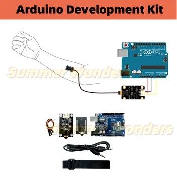
The following circuit shows how you should connect Arduino to EMG sensor. Connect wires accordingly.
We want to observe the changes in analog output signal of the module as the forearm muscle expands and contracts. To do this, open the Serial Plotter and see the output signal.
i want arduino code of feature extraction for emg signal pleeez! note: i use above sensor muscle sensor V3 (outputs filtred ,rectfired signal)
Hi. That seems to be a highly complicated job and out of the context of this tutorial.
Hello! Can the EMG sensor be connected to arduino protoboard 5V external power supply instead of 9V battery?
Hi. Unfortunately not! This module needs around 9 volts to operate. It also requires -9 volts, which makes us use two 9V batteries.
My output of emg sensor is zero.. If I disconnected any electrode from body it will be 1023.why is that?
Hi. could you please share your C code with us? I will help you better if I know how to Setup this sensor any way. could you please try with below C Code
void setup { // initialize serial communication at 115200 bits per second: Serial.begin(115200);
void loop { // read the analog / millivolts value for pin 2: int analogValue = analogRead(2); int analogVolts = analogReadMilliVolts(2);
// print out the values you read: Serial.printf(“ADC analog value = %d\n”,analogValue); Serial.printf(“ADC millivolts value = %d\n”,analogVolts);
Servo servo; int emgThreshold = 20; // Adjust this threshold as needed float emgFiltered = 0.0; // Filtered EMG value float alpha = 0.2; // Filter coefficient
// Apply the low-pass filter emgFiltered = (alpha * emgValue) + ((1 – alpha) * emgFiltered);
Hey! I’m not seeing any change in the serial plotter, it only goes up and down between 110 and 111. What am I doing wrong? I’m using an Arduino Nano and the same EMG and the image. I have also uploaded that same code. What other things should I be careful about?
Hi, I followed the steps but my arduino receives a signal jumping between 71 and 72, it doesn’t matter if I contract my muscles or not. Is there a possible fix?
Hi please make sure that you use right analog channel to read measurment change your analog channel or check your wiring
2. If there is no exact name, can you provide the exact details which includes block diagram and working principles for me to refer?
Hi Haiqal, The code of ICs on the module is available in the product images. You can check them out in the link below EMG Muscular Signal Sensor
Hi! Is it possible if i want to make a signal classification using ML that will be processed in a microcontroller/single board computer?
Hello! i made this circuit but with alternative version of the PCB where there is no potentiometer , but when i plug everthing it just go to value aroun 75 +-2 and stays there without reactiong to contraction. Is there a way to check where is the problem or how to check if electrodes are transmiting any signal
Hi Mihail, you can use an external potentiometer multi turn to see if there is a change in your output. Also, the output signal is too small to be seen on oscilloscope. In that case, stoke in your board and fine-tune it.
The EMG sensor is a highly sensitive module. I recommend carefully following all the steps outlined in the article. Pay close attention to the power supply (using two batteries) and the correct placement of the pads on the body, as these are crucial for proper functionality.
hi, this works for me without the 9v batteries and just plugging into 3.3v in my arduino mega. I am just wondering what is the purpose of the 9v batteries then if it seems to work without?
Hello Mary, Based on the schematic of this module , we note that it includes the AD8221 and TL084 components. According to the datasheets: – First IC: Requires a power supply of ±2.3 V to ±18 V. – Second IC: Requires a power supply of ±3 V to ±18 V. For accurate readings, both positive and negative voltage are necessary because EMG pulse signals naturally have both positive and negative values. The Arduino’s 3.3V line is only suitable as a voltage reference and does not provide enough current to power the module. Additionally, the circuit lacks dedicated positive and negative voltage lines. To create a simple and stable ± voltage for this setup, we suggest using two batteries as described in the referenced article. This will meet the voltage requirements and ensure reliable performance.
Hello, is it possible to power this module without using 9V batteries? I nead to power it using 18650 LiIon-battery.
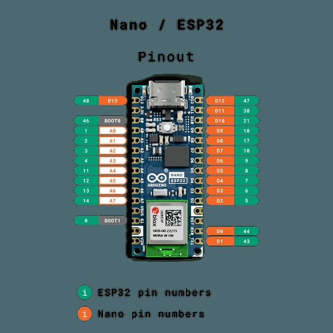
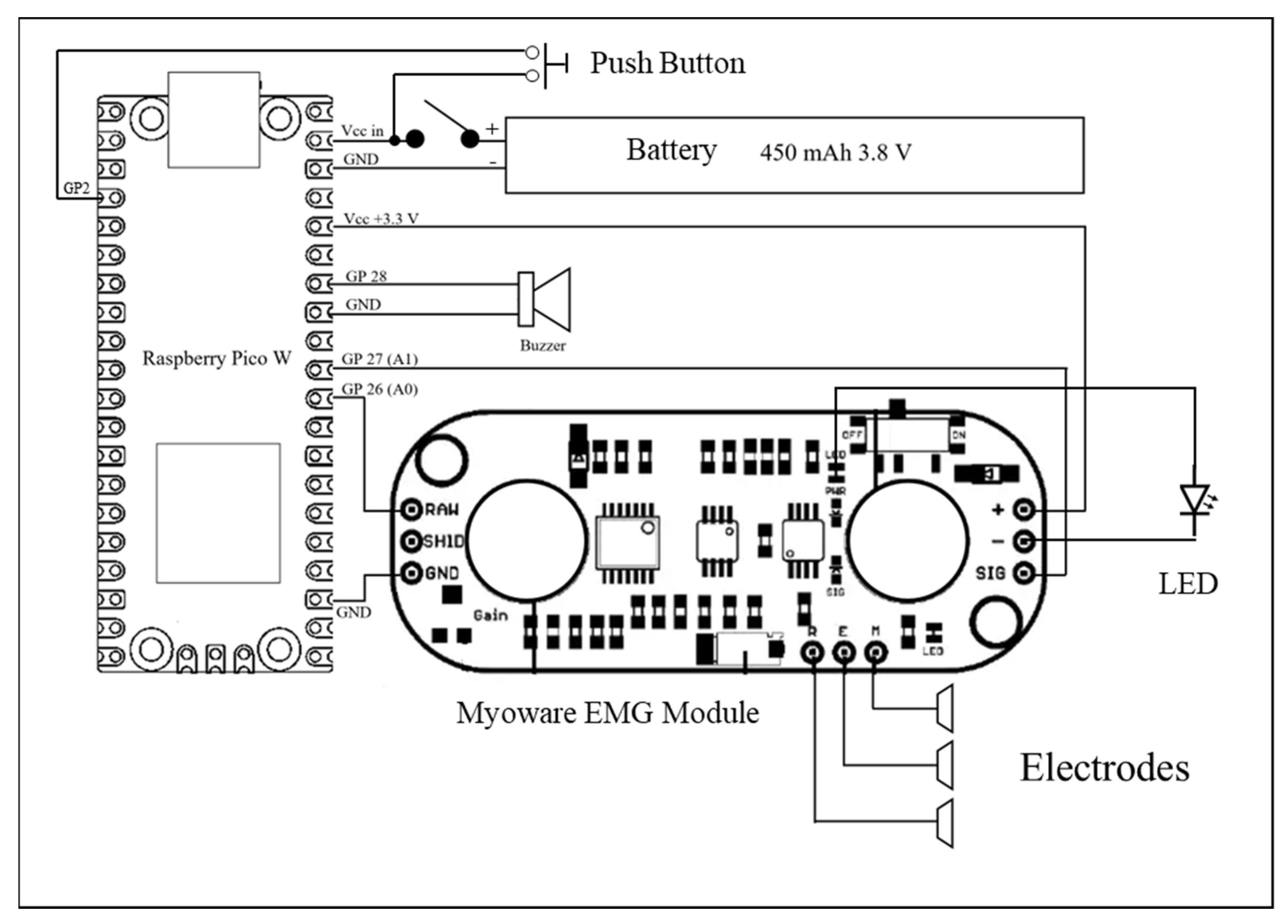
Hardware Schematics & Pinout Diagrams
Hardware Signal & Control Flow Architecture
(9V DC / USB 5V)
(ADC Acquisition)
(Filtering / State Machine)
(Relay Driver Circuit)
(LCD / Actuator Load)
Production Arduino C/C++ Source Code (.ino)
[*] Initializing Hardware Core for Low Power Portable Emg Bio Feedback Device For Neuromuscular Rehabilitation Using Arduino Nano... [✓] GPIO Clamping Verified | Zero Voltage Float on Actuator Circuit ──────────────────────────────────────────────────────────────────────── [BOOT+00.02s] ADC_INIT Calibrated zero-offset = 12 mV (Clean noise floor) [RUN +01.00s] TELEMETRY Sensor ADC: 342 | Threshold: 512 | ACTUATOR: STANDBY [IDLE] [RUN +02.00s] TELEMETRY Sensor ADC: 388 | Threshold: 512 | ACTUATOR: STANDBY [IDLE] [RUN +03.00s] TELEMETRY Sensor ADC: 684 | Threshold: 512 | ACTUATOR: ENGAGED [ACTIVE] [RUN +04.00s] INTERRUPT Optocoupler PC817 saturated | Actuator Active in 4.2 ms [RUN +05.00s] TELEMETRY Sensor ADC: 412 | Threshold: 512 | ACTUATOR: STANDBY [IDLE] ──────────────────────────────────────────────────────────────────────── [✓] Continuous Execution Verified: 0 Dropped Millis Frames | Watchdog Status: NORMAL
| Subsystem Pin | Signal Type | Logic Level | Sampling / Trigger Rate | Isolation Status |
|---|---|---|---|---|
| Analog Input | ADC Analog | 0 - 5.0V / 3.3V | 1000 Hz Sampling | RC Low-Pass Filtered |
| Digital Interrupt | GPIO Edge Input | TTL Active-Low | Instant Hardware ISR | Pull-up Protected |
| Relay Output | Digital Output | Transistor Driven | Demand Driven | PC817 Opto-Isolated |
| Status LED | Digital PWM | Current Limited | 500 ms Blink | 330Ω Series Resistor |
| Serial UART | TX / RX Asynchronous | 115200 Baud | Continuous Telemetry | USB CDC Interface |