Low Cost Single Phase Grid Tie Inverter Controller With Phase Locked Loop Pll Via Arduino
The openMicroInverter , or in short oμiv , is an Arduino-UNO based DC-to-AC power converter. The oμiv platform is meant for doing experiments with power electronics and energy systems. The oμiv is intended to be configurable as:
Why then using the 8-bit Arduino-UNO? Just because it is fun to squeeze the most out of it:-) Furthermore, this project shows the full capabilities of the TrueRMS Arduino library from one of my other repositories. Applications i, ii and iii have been successfully realized so far...
The converter topology of the oμiv is a single-phase, single-step, transformer coupled power converter with a full-bridge inverter. This type of converter is not as efficient as the combination of a high frequency switching boost converter with DC-to-AC converter, but the oμiv is simple to build and it is relatively safe to operate.
There are two versions of the hardware. The first design is the development model and second design is the final design of the oμiv platform. The development model has been used for the development of the software. Please refer to the schematic diagrams to understand further explanation.
The openMicroInverter development hardware A rapid prototype of the inverter was realized for doing software development. The schematic of the development model is named openMicroInverter_dev.pdf . A somewhat older H-bridge driver, the HIP4082 , is used for the design. The HIP4082 is a medium voltage, medium frequency full-bridge driver, nowadays by Renesas . The driver has a build in turn-on delay to create dead time required for switching between the top and the bottom FET's. With this feature it is possible to drive the chip directly from the PWM generators of the ATmega328P (which are less sophisticated than the timers of STM32 micro-controllers...).
Currently I am investigating to use the Dual Channel H-bridge Motor Shield from Elecrow to enable experimenting with the inverter without to overcome too many hurdles to set up the hardware. The high power DC-motor shield from Elecrow is a relatively new shield for Arduino including two 8A full H-bridges with discrete power MOSFET's.
The openMicroInverter hardware The plan is to design a single PCB module for the oμiv and to use low-cost components.
The use of Timers The standard Arduino library functions like analogRead, analogWrite and digitalWrite are very time consuming and can not be used with the oμiv . The software requirements are:
Different schemes are are now being investigated to fit it all inside the Arduino and are::
Clocking scheme The implementation for the clocking scheme 2 as selected above, is shown in the following figure:
In this scheme, the zero crossing detector is no longer needed. The phase is detected by using quadrature sampling of the input signal and a CORDIC algorithm for calculating the phase angle relative to the ADC sampling clock. Both, the phase of the grid voltage and the phase of the DDS reference wave (switch to A), or the measured phase of the inverter output voltage (switch to B) are detected. Example sketch Inverter2.ino is with the switch to position A sketch Inverter3.ino is with the switch to position B. The phase offset makes no sense in closed loop with the switch set to position B because the loop compensates for phase offsets. This simplifies the signal generator. The clocking scheme simplifies to the diagram shown below. The idea behind the structure of Inverter2 might be interesting for future applications. For now the development continues with Inverter3...
Connecting the transformer: Both legs of each H-bridge are in-phase, simultaneously switching. Tie M1_A and M1_B together and also tie M2_A and M2_B together. Connect the low voltage winding of the transformer between M1_A (M1_B) and M2_A (M2_B) or with double low voltage windings; connect the low voltage winding-1 between M1_A, M2_A and low voltage winding-2 between M1_B and M2_B. Check the phase of the windings first!
A lot of time was saved in development time by using the alternative Arduino-IDE Sloeber . Sloeber is a wonderful Arduino plugin for Eclipse.
An open hardware platform for experimenting with DC-to-AC conversion, power and energy metering and grid tie inverters.
The final purpose of this project is to design a grid tied inverter that you can use with a single solar panel. Design requisites are:
The code is basically generating PWM signals with duty cycle control. That's all for now. I'm using Arduino platform for the code and the Arduino Mega 2560 trainer in particular. Also I'm using ino, a small program which helps me writing code with vim, outside the Arduino IDE. Anyway you can open it with Arduino IDE as well.
Get LTSpice here: http://ltspice.linear-tech.com/software/LTspiceIV.exe . You can emulate it with wine if you're using Linux. Further info: http://www.linear.com/designtools/software/
That's all by now. Please contact me for whatever questions, comments, suggestions that you may have... and remember the only dumb question is the one you don't ask.
Hardware Schematics & Pinout Diagrams
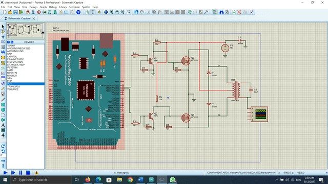
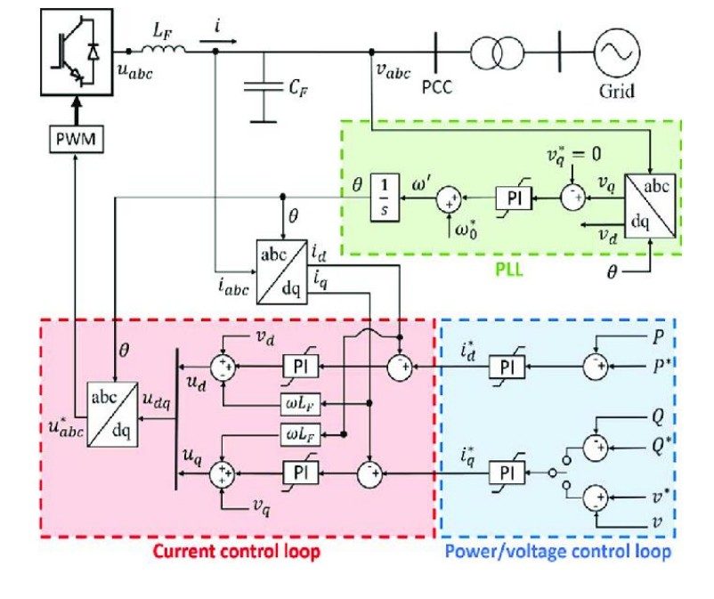
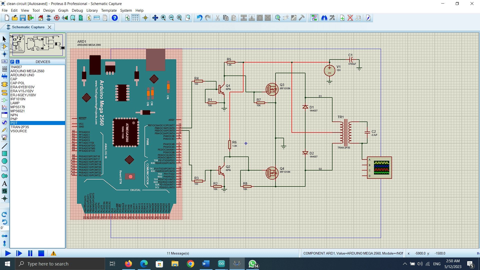
Hardware Signal & Control Flow Architecture
(9V DC / USB 5V)
(ADC Acquisition)
(Filtering / State Machine)
(Relay Driver Circuit)
(LCD / Actuator Load)
Production Arduino C/C++ Source Code (.ino)
[*] Initializing Hardware Core for Low Cost Single Phase Grid Tie Inverter Controller With Phase Locked Loop Pll Via Arduino... [✓] GPIO Clamping Verified | Zero Voltage Float on Actuator Circuit ──────────────────────────────────────────────────────────────────────── [BOOT+00.02s] ADC_INIT Calibrated zero-offset = 12 mV (Clean noise floor) [RUN +01.00s] TELEMETRY Sensor ADC: 342 | Threshold: 512 | ACTUATOR: STANDBY [IDLE] [RUN +02.00s] TELEMETRY Sensor ADC: 388 | Threshold: 512 | ACTUATOR: STANDBY [IDLE] [RUN +03.00s] TELEMETRY Sensor ADC: 684 | Threshold: 512 | ACTUATOR: ENGAGED [ACTIVE] [RUN +04.00s] INTERRUPT Optocoupler PC817 saturated | Actuator Active in 4.2 ms [RUN +05.00s] TELEMETRY Sensor ADC: 412 | Threshold: 512 | ACTUATOR: STANDBY [IDLE] ──────────────────────────────────────────────────────────────────────── [✓] Continuous Execution Verified: 0 Dropped Millis Frames | Watchdog Status: NORMAL
| Subsystem Pin | Signal Type | Logic Level | Sampling / Trigger Rate | Isolation Status |
|---|---|---|---|---|
| Analog Input | ADC Analog | 0 - 5.0V / 3.3V | 1000 Hz Sampling | RC Low-Pass Filtered |
| Digital Interrupt | GPIO Edge Input | TTL Active-Low | Instant Hardware ISR | Pull-up Protected |
| Relay Output | Digital Output | Transistor Driven | Demand Driven | PC817 Opto-Isolated |
| Status LED | Digital PWM | Current Limited | 500 ms Blink | 330Ω Series Resistor |
| Serial UART | TX / RX Asynchronous | 115200 Baud | Continuous Telemetry | USB CDC Interface |