Low Cost Scada Remote Terminal Unit Rtu Communicating Over Modbus Rtutcp On Arduino
Modbus is a protocol that uses to communicate between device and device, device and software/app, and devices to HMI. It is widely used in industrial areas to control/monitor devices.
In a simple word, Modbus is a language that a device uses to communicate with other devices, software/app, and HMI device.
This tutorial is about Arduino, so Arduino represents for the device . By using Modbus, we can make:
For example, Arduino #1 with 4 switches controls Arduino #2 with 4 light bulbs over a long distance.
To answer these questions, let's consider a case: A switch connected to Arduino #1 controls an LED connected to Arduino #2 over a long distance.
The simplest alternative way of Modbus is to define a simple protocol by ourselves:
The above protocol is defined by ourselves, not a standard protocol. We need to define more if:
It is not easy to define all commands by ourselves. The problem becomes more complicated when we mix the above requirements. And we also cannot guarantee error-free
Another problem occurs when defining the protocol by ourselves. If we want our Arduino to work with other Arduino used a protocol defined by another person, It is impossible unless we co-work and share the self-defined protocol.
Those are the reasons why we need Modbus protocol. If we use the Modbus protocol:
If we use the Modbus protocol for Arduino, we can use many free software/app to control/monitor our Arduino.
Modbus protocol is not easy for beginners to understand and implement it, even the Modbus library is available. Therefore, it is ok to use a simple self-defined protocol as described above if:
There are some other standard protocols and non-standard protocols that are alternatives for Modbus. They are out of the scope of this tutorial.
As described earlier, An Arduino can communicate with software/app, HMI device, or another Arduino via Modbus protocol. This tutorial takes communication between two Arduino as an example of Modbus communication. The others are the same.
Modbus protocol works in the Master - Slave model. Among two Arduino, one MUST work as a Master , and the other works as a Slave .
Once receiving a request , the Slave takes the corresponding action and send back a response which contains the result of action or the information that Master requested.
The Function Code was defined by the Modbus standard. There are many Function Code . Let's see some basic Function Code below:
There are more Function Code . In order to avoid overloading newbies, this tutorial only present some essential Function Code .
The detailed instruction of using Modbus library will be presented in the next tutorial, like our Facebook page to get the new tutorial notification.
Arduino Master can read the state of its digital input pin, and then control the digital output's state of Arduino Slave , and vice versa
There are three popular Modbus types: Modbus RTU, Modbus ASCII, and Modbus TCP. The working principles are the same for all of Modbus types, as described above. Each type of Modbus is designed to adapt to the network environment: Serial or TCP.
We are going to make a tutorial about how to use Modbus library. Like our Facebook page to get the new tutorial notification.
Turning an Arduino into a Modbus RTU slave is a common way to bridge cheap sensors or actuators into an existing PLC/SCADA network without buying a dedicated field device. It takes one extra piece of hardware — an RS-485 transceiver — and a library that handles the RTU framing and direction-pin timing for you. This guide covers wiring, library choice, register mapping, and how to test the result against a simulated Modbus master before it ever touches a real PLC.
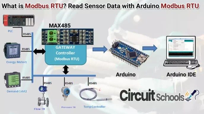
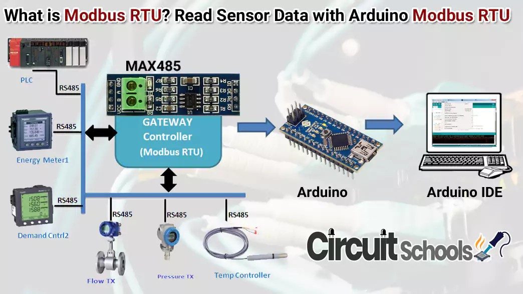
Arduino has no native RS-485 port, so Modbus RTU requires a small transceiver module — almost always built around a MAX485 or MAX3485 chip:
The DE/RE pin is what makes RS-485 half-duplex work on a microcontroller: drive it high right before transmitting a response, then low again immediately after the last byte clears the UART so the module goes back to listening. Getting this timing wrong is the single most common source of corrupted Modbus frames on Arduino builds.
An Uno or Nano has exactly one hardware UART, on pins 0/1 — the same port used for USB programming and Serial Monitor debugging. Wiring RS-485 directly to those pins means you lose your debug console and can interfere with sketch uploads. Most Uno/Nano builds instead run the RS-485 module on a SoftwareSerial port on two other pins (reliable up to roughly 38400 baud), while boards with multiple independent hardware UARTs, like the Mega, can dedicate a real hardware serial port to Modbus and keep USB Serial free for debugging.
Before wiring your Arduino into a live PLC or SCADA network, it's worth confirming the register map and function-code support independently:
This is the same simulate-before-you-wire-it-up approach covered for other constrained hardware in our Raspberry Pi Modbus slave guide , just adapted to RS-485/RTU instead of Ethernet/TCP.
Modbus Simulator runs as a Modbus RTU or TCP master (or slave) on your PC, so you can validate your Arduino's register map and function-code handling — before it's wired into a live PLC or SCADA network. Free 30-day trial.
Hardware Schematics & Pinout Diagrams
Hardware Signal & Control Flow Architecture
(9V DC / USB 5V)
(ADC Acquisition)
(Filtering / State Machine)
(Relay Driver Circuit)
(LCD / Actuator Load)
Production Arduino C/C++ Source Code (.ino)
[*] Initializing Hardware Core for Low Cost Scada Remote Terminal Unit Rtu Communicating Over Modbus Rtutcp On Arduino... [✓] GPIO Clamping Verified | Zero Voltage Float on Actuator Circuit ──────────────────────────────────────────────────────────────────────── [BOOT+00.02s] ADC_INIT Calibrated zero-offset = 12 mV (Clean noise floor) [RUN +01.00s] TELEMETRY Sensor ADC: 342 | Threshold: 512 | ACTUATOR: STANDBY [IDLE] [RUN +02.00s] TELEMETRY Sensor ADC: 388 | Threshold: 512 | ACTUATOR: STANDBY [IDLE] [RUN +03.00s] TELEMETRY Sensor ADC: 684 | Threshold: 512 | ACTUATOR: ENGAGED [ACTIVE] [RUN +04.00s] INTERRUPT Optocoupler PC817 saturated | Actuator Active in 4.2 ms [RUN +05.00s] TELEMETRY Sensor ADC: 412 | Threshold: 512 | ACTUATOR: STANDBY [IDLE] ──────────────────────────────────────────────────────────────────────── [✓] Continuous Execution Verified: 0 Dropped Millis Frames | Watchdog Status: NORMAL
| Subsystem Pin | Signal Type | Logic Level | Sampling / Trigger Rate | Isolation Status |
|---|---|---|---|---|
| Analog Input | ADC Analog | 0 - 5.0V / 3.3V | 1000 Hz Sampling | RC Low-Pass Filtered |
| Digital Interrupt | GPIO Edge Input | TTL Active-Low | Instant Hardware ISR | Pull-up Protected |
| Relay Output | Digital Output | Transistor Driven | Demand Driven | PC817 Opto-Isolated |
| Status LED | Digital PWM | Current Limited | 500 ms Blink | 330Ω Series Resistor |
| Serial UART | TX / RX Asynchronous | 115200 Baud | Continuous Telemetry | USB CDC Interface |