Low Cost Regenerative Braking Simulator Rig With Inertia Flywheels And Arduino Data Logger
Electric vehicles recover energy when braking because their motors can run backwards as generators. This project demonstrates the principle on a bench rig: a DC motor belt-coupled to a heavy flywheel is spun up, then the drive is switched to generator mode and the flywheel's kinetic energy is converted back into charging current for a battery, measured live on a multimeter and an LCD. It ships with a working rig, control firmware, measurement procedure, report, PPT and viva Q&A. Suitable for B.E./B.Tech final-year projects in Electrical and Mechanical.
When an electric vehicle brakes, its motor controller reverses the power flow: the motor becomes a generator, the car's kinetic energy becomes electrical energy, and the battery recharges instead of the energy being wasted as heat in brake pads. Students hear this in EV courses but rarely see the energy actually flow back. This project makes it visible on a bench rig: a DC motor on an aluminum frame is belt-coupled to a heavy flywheel disc. The motor spins the flywheel up (motoring mode); then the controller switches to generator mode, the flywheel drives the motor as a generator, and the generated current flows into a Li-ion battery pack through the driver — with speed and regenerated current shown live on an LCD and a multimeter. The student measures spin-up energy versus recovered energy and computes the round-trip efficiency themselves.
H-bridge that powers the motor in spin-up and routes generated current to the battery when braking.
Stores kinetic energy visibly; its spin-down during braking is the energy transfer on show.
Supplies spin-up energy and receives the regenerated charge through its protection circuit.
Into the 3S Li-ion battery pack: the generator-mode current flows through the driver into the pack, and the multimeter shows it live. The flywheel visibly slows as its kinetic energy becomes charge.
Every conversion loses energy — belt friction, bearing drag, copper and iron losses in the machine, driver switching losses, battery charge inefficiency. The procedure has the student account for each, which is excellent viva material.
Shorting (dynamic braking) dumps the energy as heat in the windings. Regenerative braking routes it into the battery instead — same braking effect, recovered energy.
Yes — the firmware sets the generator loading, which sets the electrical braking torque. Light loading gives gentle, long braking; heavy loading stops the flywheel fast with higher peak current.
The pack has a protection circuit (overcharge/overcurrent), the driver current-limits the charge path, and the manual's safety rules cover handling. Mains power is not involved anywhere.
Yes — for Electrical and Mechanical programs. It demonstrates electric machines, energy conversion, power electronics and experimental efficiency measurement.
This project builds a bench demonstration panel with two inverse-time overcurrent relay stages that show how protection gradi...
This project builds a Motor Winding Temperature Monitor with PT100 and Relay Trip for Industrial Motors that measures winding...
This project builds a Single-Phase Motor Protection Panel using an Arduino, an ACS712 current sensor and a ZMPT101B voltage s...
Ten real, published projectech.in listings: motor-control and drives builds from soft starters and DOL trainer panels to VFD crane controls and current-signature fault diagnosis — each with the problem, the working and why students pick it.
A soft starter tames the first seconds of a motor start by ramping voltage gradually through thyristors, then handing over to a bypass contactor. This guide explains the ramp, current limit and soft stop settings, works through a nameplate sizing example, and compares soft starters with direct-on-line, star-delta and VFD starting.
That small metal plate on every induction motor lists its rated power, voltage, full-load current, speed, duty type, insulation class, IP rating and efficiency class. This guide decodes each field, explains the decisions each number drives — starter type, cable size, overload relay setting — and works through one complete example nameplate end to end.
A prototype demonstrating how braking behavior affects the energy of a moving system and how rotational energy can be converted into electrical energy during braking.
This project demonstrates the working principle of regenerative braking using an Arduino-based prototype.
Unlike a simple motor speed control project, this system focuses on how driver braking behavior influences the motion of a rotating system and how energy can be generated while slowing it down.
The DC motor represents a vehicle wheel. As the wheel rotates, it possesses kinetic energy . When braking is applied through a potentiometer (acting as a brake pedal), the Arduino interprets the braking intensity and reduces the motor speed accordingly.
During deceleration, the motor continues spinning due to inertia. At this stage, it behaves like a small generator and produces electrical energy. This generated energy is visually indicated using an LED, while a voltage sensor provides measurable electrical data.
This prototype demonstrates the concept of regenerative braking rather than implementing a complete battery charging system.
A short demonstration video showing the complete operation of the Driver-Intent-Based Regenerative Braking System, including motor operation, driver-controlled braking using the potentiometer, LED indication during regenerative braking, and the overall working prototype.
Instead of stopping the motor instantly, the Arduino adjusts the PWM signal according to the brake input.
This demonstrates the basic principle behind regenerative braking used in electric vehicles.
According to the brake position, it generates a PWM signal to control the L298N motor driver.
As braking increases, the Arduino reduces PWM duty cycle, decreasing motor speed.
This generated voltage passes through a diode to protect the circuit and drives an LED.
This prototype is designed to demonstrate the concept of regenerative braking rather than replicate the exact behavior of a commercial electric vehicle.
Real vehicles have significantly greater mass, causing braking and energy recovery to occur more gradually.
Despite this, the LED and voltage sensor clearly demonstrate that energy is produced during deceleration.
Although a lithium-ion battery is physically placed on the prototype board, it is intentionally not connected to the regenerative braking circuit and does not participate in the operation of the project .
Its presence is only for demonstration purposes to represent the battery found in a real electric vehicle.
Implementing safe battery charging requires additional hardware such as DC-DC converters, charging circuits, current limiting, voltage regulation, and battery protection, which are beyond the scope of this educational prototype.
For stable operation, this project instead uses an external power supply for the motor and Arduino, while the generated energy is demonstrated using the LED and voltage sensor.
This project successfully demonstrates the fundamental principle of driver-intent-based regenerative braking . By allowing the user to vary braking intensity using a potentiometer, the Arduino dynamically controls motor deceleration. As the motor slows due to inertia, it produces electrical energy that is indicated through an LED and monitored by a voltage sensor. Although the generated energy is not stored in a battery, the prototype effectively illustrates how regenerative braking converts a portion of a moving system's kinetic energy into electrical energy. The setup serves as an educational model for understanding the core concepts of regenerative braking used in electric vehicles.
Regenerative system based on driver's intention while braking thereby controlling regenerative system.
A smart micro-controller setup demonstrating vehicle speed regulation, mechanical braking, and kinetic energy recovery (regenerative braking) with real-time battery diagnostics and visual feedback.
The Arduino Uno sits at the center of the system, polling the potentiometer value (acceleration input) and the push button (brake input). It uses these signals to govern the DC motor driver and updates the system state and battery logs accordingly.
The schematic details connections between the Arduino Uno, the transistor-driven DC motor speed controller, and the feedback systems.
Triggered when the accelerator pedal (potentiometer) is at its starting minimum position and the brakes are not engaged.
This project is a simulation-based prototype built inside Tinkercad. The regenerative recovery and charging algorithms are simulated logically within the code to demonstrate energy harvesting concepts.
Arduino-based EV regenerative braking system with real-time battery monitoring using Tinkercad simulation
Build a rig where the motor turns into a generator when you brake and sends energy back into a battery. Measure how much energy you get back at different speeds.
Hardware Schematics & Pinout Diagrams
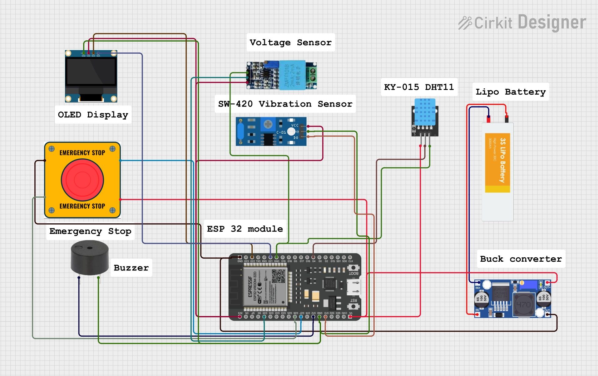
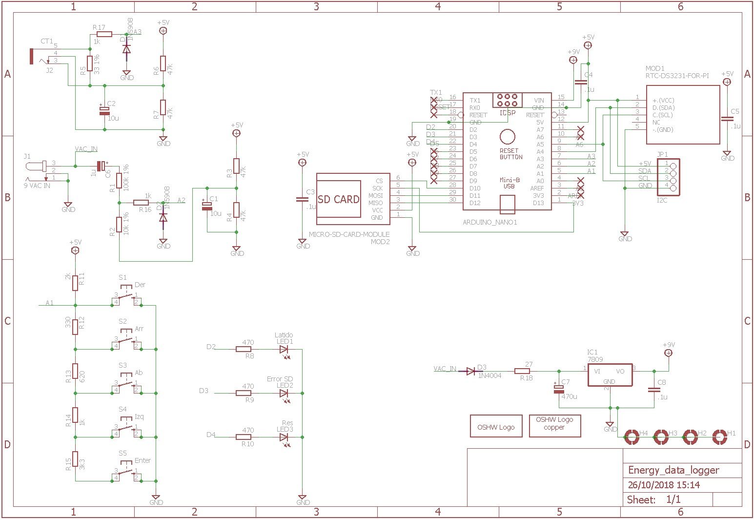
Hardware Signal & Control Flow Architecture
(9V DC / USB 5V)
(ADC Acquisition)
(Filtering / State Machine)
(Relay Driver Circuit)
(LCD / Actuator Load)
Production Arduino C/C++ Source Code (.ino)
[*] Initializing Hardware Core for Low Cost Regenerative Braking Simulator Rig With Inertia Flywheels And Arduino Data Logger... [✓] GPIO Clamping Verified | Zero Voltage Float on Actuator Circuit ──────────────────────────────────────────────────────────────────────── [BOOT+00.02s] ADC_INIT Calibrated zero-offset = 12 mV (Clean noise floor) [RUN +01.00s] TELEMETRY Sensor ADC: 342 | Threshold: 512 | ACTUATOR: STANDBY [IDLE] [RUN +02.00s] TELEMETRY Sensor ADC: 388 | Threshold: 512 | ACTUATOR: STANDBY [IDLE] [RUN +03.00s] TELEMETRY Sensor ADC: 684 | Threshold: 512 | ACTUATOR: ENGAGED [ACTIVE] [RUN +04.00s] INTERRUPT Optocoupler PC817 saturated | Actuator Active in 4.2 ms [RUN +05.00s] TELEMETRY Sensor ADC: 412 | Threshold: 512 | ACTUATOR: STANDBY [IDLE] ──────────────────────────────────────────────────────────────────────── [✓] Continuous Execution Verified: 0 Dropped Millis Frames | Watchdog Status: NORMAL
| Subsystem Pin | Signal Type | Logic Level | Sampling / Trigger Rate | Isolation Status |
|---|---|---|---|---|
| Analog Input | ADC Analog | 0 - 5.0V / 3.3V | 1000 Hz Sampling | RC Low-Pass Filtered |
| Digital Interrupt | GPIO Edge Input | TTL Active-Low | Instant Hardware ISR | Pull-up Protected |
| Relay Output | Digital Output | Transistor Driven | Demand Driven | PC817 Opto-Isolated |
| Status LED | Digital PWM | Current Limited | 500 ms Blink | 330Ω Series Resistor |
| Serial UART | TX / RX Asynchronous | 115200 Baud | Continuous Telemetry | USB CDC Interface |