Low Cost Battery Capacity Discharge Tester With Constant Current Sink Controlled By Arduino
Nowadays fake Lithium and NiMH batteries are everywhere which is sold by advertising with higher capacities than their true capacity. So it is really difficult to distinguish between a real and a fake battery. Similarly, it is difficult to know the capacity retained in the salvaged 18650 laptop batteries. So, a device is required to measure the true capacity of the batteries.
In the year 2016, I have written an tutorial on " Arduino Capacity Tester - V1.0 " which was a very straight forward and simple device. The earlier version was based on Ohms Law. The battery to be tested is discharged through a fixed resistor, current and time duration is measured by Arduino Nano and capacity is calculated by multiplying both the readings ( Discharge current and time ).
The drawback of the earlier version was that during the testing, as as the battery voltage decrease, the current also decreases which make the calculations complex and inaccurate. To overcome this, I have made the V2.0 which is designed in such a way that the current will remain constant throughout the discharging process. I made this device by inspiring the original design by MyVanitar
1. Capable of measuring the capacity of AA / AAA NiMh / NiCd, 18650 Li-ion, Li-Polymer, and Li FePO4 battery. It is suitable for almost any kind of battery rated below 5V.
Disclaimer: Please note that you are working with Li-Ion battery which is highly explosive and dangerous. I cannot be held responsible for any loss of property, damage, or loss of life if it comes to that. This tutorial was written for those who have knowledge of rechargeable lithium-ion technology. Please do not attempt this if you are a novice. Stay Safe.
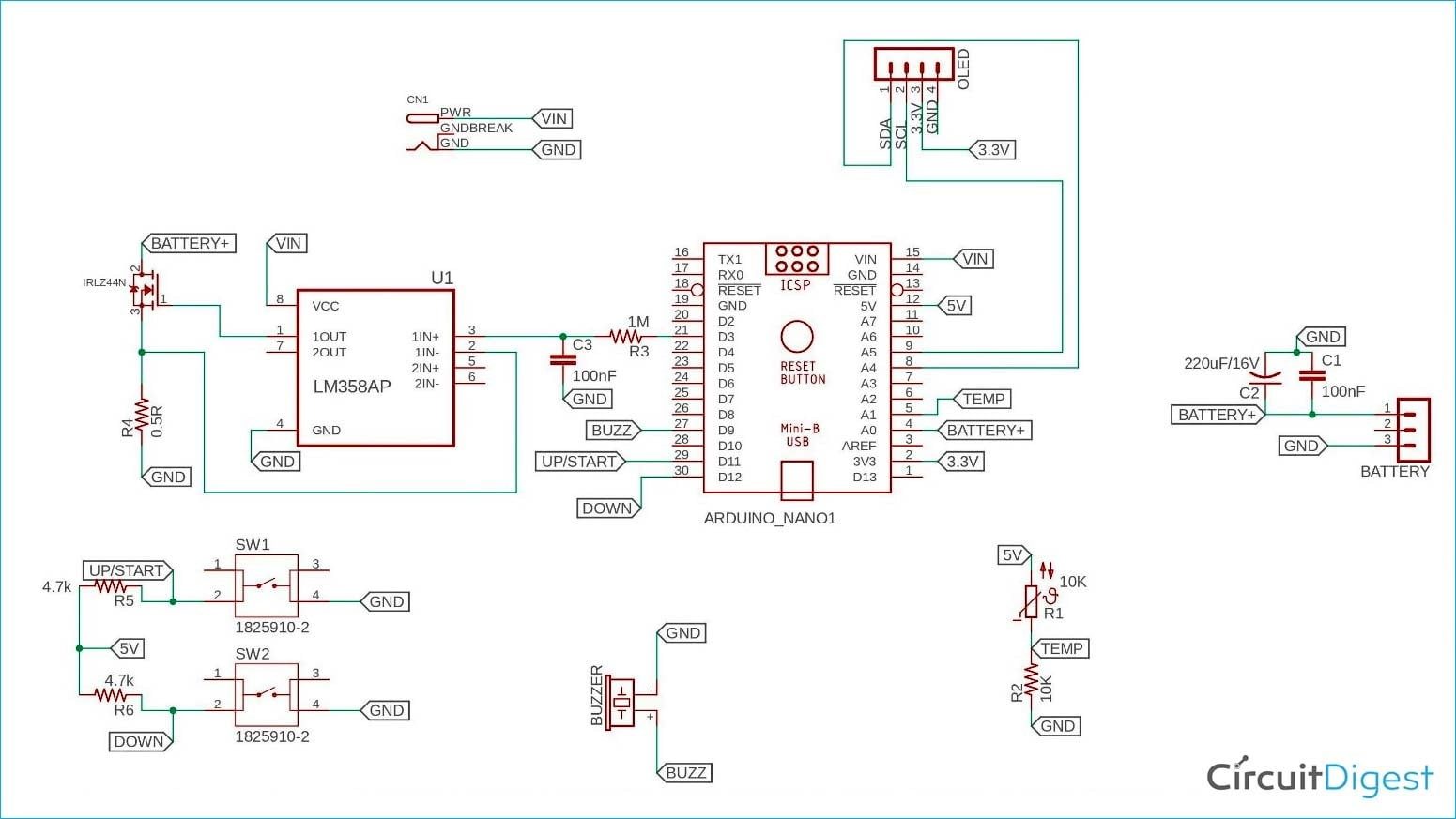
The power supply circuit is consists of a DC Jack ( 7-9V) and two filter capacitors C1 and C2. The power output (Vin) is connected to the Arduino pin Vin. Here I am using the Arduino on-board voltage regulator to step down the voltage to 5V.
The core component of the circuit is Op-amp LM358 which contains two operational amplifiers. The PWM signal from the Arduino pin D10 is filtered by a low-pass filter ( R2 and C6 ) and fed to the second operational amplifier. The output of the second op-amp is connected to the first op-amp in voltage follower configuration. The power supply to LM358 is filtered by a decoupling capacitor C5.
The first op-amp, R1, and Q1 build a constant current load circuit. So now we can control the current through the load resistor (R1) by changing the PWM signal pulse width.
The battery voltage is measured by the Arduino analog input pin A0. Two capacitors C3 and C4 are used to filter out the noises coming from the constant current load circuit which can degrade the ADC conversion performance.
The user interface circuit is consists of two push-buttons and a 0.96" I2C OLED display. The Up and Down push-button is to increase or decrease the PWM pulse width. R3 and R4 are pull-up resistors for the Up and Down push-buttons. C7 and C8 are used to debounce the push-buttons. The third push-button (RST) is used for resetting the Arduino.
The buzzer circuit is used to alert the starting and end of the test. A 5V buzzer is hooked to Arduino digital pin D9.
The theory is based on the voltage comparison of the inverting (pin-2) and the non-inverting (pin-3) inputs of the OpAmp, configured as a unity amplifier. When you set the voltage applied to the non-inverting input by adjusting the PWM signal, the output of the opamp opens the gate of MOSFET. As the MOSFET turn-on, the current runs through R1, it creates a voltage drop, which provides negative feedback to OpAmp. It controls the MOSFET in such a way that the voltages at its inverting and non-inverting inputs are equal. So, the current through the load resistor is proportional to the voltage at the non-inverting input of the OpAmp.
From the above equation it is clear that to calculate battery capacity (mAh), we have to know the current in mA and time in Hour. The designed circuit is a constant current load circuit, so the discharge current remains constant throughout the testing period.
The discharge current can be adjusted by pressing the Up and Down Button. The time duration is measured by using a timer in the Arduino code.
For Soldering, you will need a decent Soldering Iron, Solder, Nipper and a multimeter. It is good practice to solder the components according to their height. Solder the lesser height components first.
2. Hold the tip of the soldering iron to the junction of the pad and the leg of the component.
3. Feed solder into the joint so that it flows all around the lead and covers the pad. Once it has flowed all around, move the tip away.
First, download the attached Arduino Code. Then download the following libraries and install them.
1. Current Arrays values: This can be done by connecting a multimeter in series with the battery. Press the up button and measure the current, the current values are the elements of the array.
2. Vcc: You use a multimeter to measure the voltage at the Arduino 5V pin. In my case it is 4.96V.
You can change the Low_BAT_Level value in the code as per the battery chemistry. It is better to take a little margin over the cut off voltage stated below.
Here is the discharge rates and cutoff voltages for various Lithium-Ion Battery chemistry:
5. Lithium Nickel Manganese Cobalt Oxide: Cut-off Voltage = 2.5V at 1C discharge rate
6. Lithium Nickel Cobalt Aluminum Oxide: Cut-off Voltage = 3.0V at 1C discharge rate
To test the circuit, first I charged a good Samsung 18650 battery using my ISDT C4 Charger . Then connect the battery to the battery terminal. Now set the current to according to your requirement and long-pressed the “UP” button. Then you should hear a beep and the test procedure starts. During the test, you will monitor all the parameters on the OLED display. The battery will discharge until its voltage reaches its low-level threshold (3.2V). The test process will be finished by two long beeps.
Note: The project is still under development stage. You can join me for any improvements. Raise comments if any mistakes or errors. I am designing a PCB for this project. Stay connected for more updates to the project.
Hardware Schematics & Pinout Diagrams
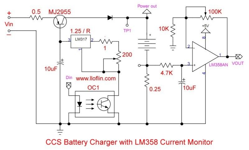
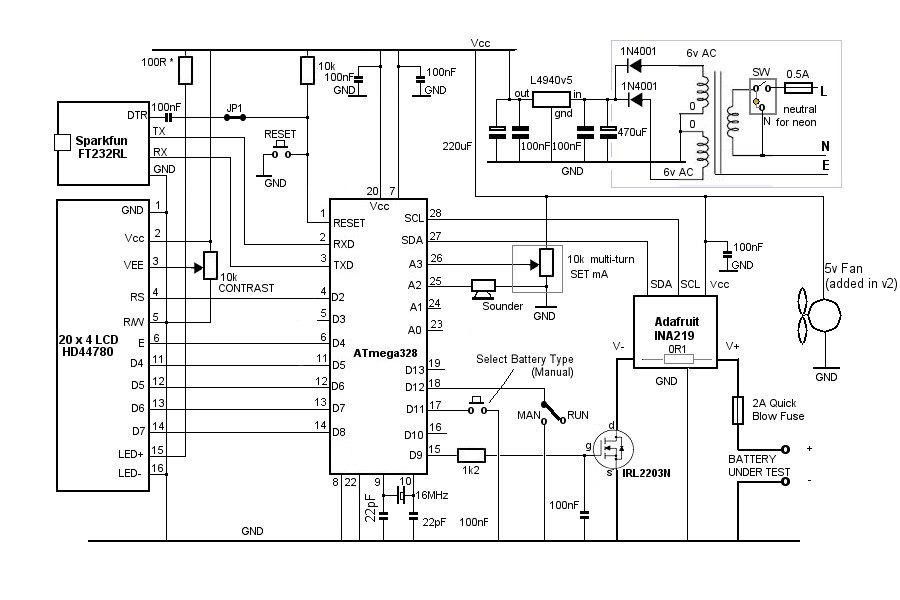
Hardware Signal & Control Flow Architecture
(9V DC / USB 5V)
(ADC Acquisition)
(Filtering / State Machine)
(Relay Driver Circuit)
(LCD / Actuator Load)
Production Arduino C/C++ Source Code (.ino)
[*] Initializing Hardware Core for Low Cost Battery Capacity Discharge Tester With Constant Current Sink Controlled By Arduino... [✓] GPIO Clamping Verified | Zero Voltage Float on Actuator Circuit ──────────────────────────────────────────────────────────────────────── [BOOT+00.02s] ADC_INIT Calibrated zero-offset = 12 mV (Clean noise floor) [RUN +01.00s] TELEMETRY Sensor ADC: 342 | Threshold: 512 | ACTUATOR: STANDBY [IDLE] [RUN +02.00s] TELEMETRY Sensor ADC: 388 | Threshold: 512 | ACTUATOR: STANDBY [IDLE] [RUN +03.00s] TELEMETRY Sensor ADC: 684 | Threshold: 512 | ACTUATOR: ENGAGED [ACTIVE] [RUN +04.00s] INTERRUPT Optocoupler PC817 saturated | Actuator Active in 4.2 ms [RUN +05.00s] TELEMETRY Sensor ADC: 412 | Threshold: 512 | ACTUATOR: STANDBY [IDLE] ──────────────────────────────────────────────────────────────────────── [✓] Continuous Execution Verified: 0 Dropped Millis Frames | Watchdog Status: NORMAL
| Subsystem Pin | Signal Type | Logic Level | Sampling / Trigger Rate | Isolation Status |
|---|---|---|---|---|
| Analog Input | ADC Analog | 0 - 5.0V / 3.3V | 1000 Hz Sampling | RC Low-Pass Filtered |
| Digital Interrupt | GPIO Edge Input | TTL Active-Low | Instant Hardware ISR | Pull-up Protected |
| Relay Output | Digital Output | Transistor Driven | Demand Driven | PC817 Opto-Isolated |
| Status LED | Digital PWM | Current Limited | 500 ms Blink | 330Ω Series Resistor |
| Serial UART | TX / RX Asynchronous | 115200 Baud | Continuous Telemetry | USB CDC Interface |