Low Cost Autonomous Guided Forklift With Pallet Optical Alignment Using Arduino Mega
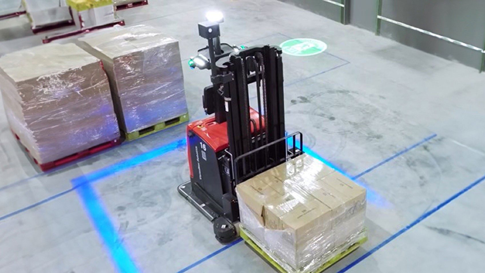
Our forklift prioritizes safety above all else. Its design incorporates precise sizes, tolerances, and detailed working drawings for every component. We conducted comprehensive stress analysis for optimal performance. The final product stands out with its appealing shape, exceptional finishing, and seamless assembly.
Our project involved an embedded system with one Arduino Mega microcontroller as data buffer between the Jetson TX2 and two Tiva-C boards. Following AUTOSAR standards, our system incorporated the MCAL, HAL, and APP drivers. The MCAL layer included functionalities such as DIO, PORT, ADC, PWM, INTCTRL, UART, and TIMERS, while the HAL layer focused on Encoder, Motor, and LED functionalities. The App layer featured a PID controller, parsing capabilities, and serialization techniques for efficient data transmission.
We integrated ROS for Navigation and Localization, leveraging sensor data to determine the robot's position and orientation. This framework empowered our robot to navigate complex environments with confidence, ensuring optimal path planning, obstacle avoidance, and efficient movement.
We employed computer vision techniques using a pretrained YOLO CNN for object detection and recognition. Our computer vision module included QR code detection and scanning using the zbar ROS package, enabling the robot to identify goal destinations for precise movements.
The successful integration of ROS for Navigation and Localization in our project has advanced our understanding of robotics and equipped us with the skills necessary to contribute to the future of autonomous systems. I am proud of my team's accomplishments and look forward to further exploring innovation in robotics, leveraging cutting-edge technologies like ROS to redefine human-robot interaction.
Abdelrahman Mahmoud Ehab Abdelrahman Mostafa Mahmoud Abdelrhman Motawea Ali Abdelrahman Omar Abdelhalem Anas Ahmed Talaat El Sayed Ayman El Sayed Mahmoud Ayman Abdelaziz Mahmoud Tariq Mahmoud Mahmoud Nassef Mohamed
this project showcases the successful development of an autonomous robotic forklift system, highlighting its potential impact on enhancing warehouse efficiency and optimizing material handling operations. The insights gained from this project contribute to the advancement of robotics technology in the field of logistics and automation.
A student-built autonomous material-handling robot that follows a guided line, picks up a box, reads a QR route command with a Raspberry Pi, selects the correct branch at a T-junction, delivers the[...]
Project status: working educational prototype for a controlled track. It is not an industrial forklift, safety-rated AMR, or certified material-handling system.
On the return trip, the Arduino automatically uses the opposite turn so the robot can return to the pickup branch.
The Raspberry Pi does not directly drive the motors. It sends the decoded route to the Arduino, while the Arduino handles real-time movement and station/junction behavior.
The firmware runs continuously until the robot is stopped or powered off; there is no automatic mission End state in the current Arduino loop.
The current firmware treats an all-clear sensor condition as a station after approximately 350 ms, so a completely lost line can also resemble a station. Keep the station geometry consistent and [...]
Important: the circuit diagram must match the firmware. In the current Arduino code, the fork servo signal is D5 , while D3 is the push button. Do not publish a schematic that labels the se[...]
The current design uses separate regulated positive rails for the Raspberry Pi and 5 V logic/servo supply. Do not tie the 5.15 V and 5.0 V positive outputs together. A common ground betwe[...]
The Arduino Mega TX pin is a 5 V logic output. Do not connect Mega TX1 directly to the Raspberry Pi RX pin; use the voltage divider or a suitable logic-level shifter shown in the schematic.
Exact motor model, wheel diameter, sensor mounting height, chassis dimensions, and fork geometry should be documented in hardware/ before calling the build fully reproducible.
This layout separates the tested firmware, Raspberry Pi software, documentation, hardware files, QR assets, and demonstration media so a new builder can find each part without searching through e[...]
Assemble the chassis with two drive motors on the left and two on the right. The two motors on each side are driven together, creating differential-drive steering.
Before powering the servo, verify that these angles do not force the linkage beyond its mechanical limits.
Mount the six IR sensors at the front/bottom of the robot with consistent spacing and height. Record the final sensor height and spacing in hardware/ so other builders can reproduce the same be[...]
The current vision program requires Python 3, OpenCV, NumPy, pyzbar , pyserial , and the ZBar runtime.
If your Pi exposes the UART under another device such as /dev/serial0 , update SERIAL_PORT accordingly.
The script displays a live OpenCV window. If you run the Raspberry Pi headless, modify the script to remove or disable the GUI calls ( cv2.imshow / keyboard window handling).
The Python script converts input to lowercase and ignores any decoded string other than l or r .
Place the QR on the box where the pickup-station camera can read it reliably during the stationary pickup period.
During calibration, the robot rotates while sampling each IR channel. Make sure the sensor array sees both the line and the background during this process.
The Raspberry Pi sends a single l or r character through UART. The current script applies a 0.3 s anti-spam interval before resending the same command.
After accepting a valid command, the Arduino sends an acknowledgement similar to:
The current Raspberry Pi script does not yet use this acknowledgement for closed-loop command confirmation; it is available for future reliability improvements.
At an outbound junction, the robot uses the saved QR route. During the return trip, the same route is kept but reversed logically:
When the robot physically reaches the pickup station again, the old route is cleared so the next box can provide a new QR command.
These values are in the Arduino firmware and may need adjustment for another chassis or track.
Do not copy these tuning values blindly to a robot with different motors, wheel diameter, battery voltage, mass, sensor spacing, or track geometry.
This project switches relatively high motor current and uses a LiPo battery. Treat it as a laboratory prototype.
The current tested firmware does not implement certified obstacle avoidance, emergency-stop logic, localization, or industrial functional safety.
Built as an educational mechatronics and autonomous material-handling project using Raspberry Pi, Arduino, computer vision, embedded control, line sensing, and differential-drive motion.
Hardware Schematics & Pinout Diagrams
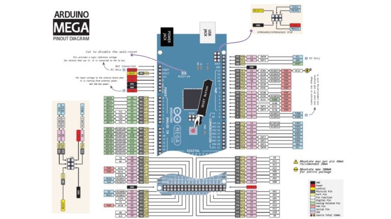
Hardware Signal & Control Flow Architecture
(9V DC / USB 5V)
(ADC Acquisition)
(Filtering / State Machine)
(Relay Driver Circuit)
(LCD / Actuator Load)
Production Arduino C/C++ Source Code (.ino)
[*] Initializing Hardware Core for Low Cost Autonomous Guided Forklift With Pallet Optical Alignment Using Arduino Mega... [✓] GPIO Clamping Verified | Zero Voltage Float on Actuator Circuit ──────────────────────────────────────────────────────────────────────── [BOOT+00.02s] ADC_INIT Calibrated zero-offset = 12 mV (Clean noise floor) [RUN +01.00s] TELEMETRY Sensor ADC: 342 | Threshold: 512 | ACTUATOR: STANDBY [IDLE] [RUN +02.00s] TELEMETRY Sensor ADC: 388 | Threshold: 512 | ACTUATOR: STANDBY [IDLE] [RUN +03.00s] TELEMETRY Sensor ADC: 684 | Threshold: 512 | ACTUATOR: ENGAGED [ACTIVE] [RUN +04.00s] INTERRUPT Optocoupler PC817 saturated | Actuator Active in 4.2 ms [RUN +05.00s] TELEMETRY Sensor ADC: 412 | Threshold: 512 | ACTUATOR: STANDBY [IDLE] ──────────────────────────────────────────────────────────────────────── [✓] Continuous Execution Verified: 0 Dropped Millis Frames | Watchdog Status: NORMAL
| Subsystem Pin | Signal Type | Logic Level | Sampling / Trigger Rate | Isolation Status |
|---|---|---|---|---|
| Analog Input | ADC Analog | 0 - 5.0V / 3.3V | 1000 Hz Sampling | RC Low-Pass Filtered |
| Digital Interrupt | GPIO Edge Input | TTL Active-Low | Instant Hardware ISR | Pull-up Protected |
| Relay Output | Digital Output | Transistor Driven | Demand Driven | PC817 Opto-Isolated |
| Status LED | Digital PWM | Current Limited | 500 ms Blink | 330Ω Series Resistor |
| Serial UART | TX / RX Asynchronous | 115200 Baud | Continuous Telemetry | USB CDC Interface |