Low Cost Automated Pet Feeder With Weight Calibrated Portions And Smartphone Notification
Feeding a pet at the right time every day can become difficult when work, travel, or other responsibilities interfere with a routine. A smart pet feeder can solve this problem by automating food dispensing according to a predefined schedule. Instead of manually measuring and serving every meal, a connected feeder can release food at selected times and, in more advanced designs, allow remote control.
Arduino makes it possible to build a customizable smart pet feeder using relatively accessible electronics and 3D-printed parts. One Arduino Project Hub design uses an Arduino UNO R4 WiFi, Arduino Plug and Make Kit, continuous servo motor, Modulino Distance, Modulino Pixels, Modulino Buzzer, Arduino Cloud, and a 3D-printed enclosure.
A smart pet feeder is an automated device designed to dispense pet food at specific times or in response to user commands. Unlike a basic food container, it combines mechanical and electronic components to control when and how food is released.
The Arduino Project Hub design demonstrates how these features can be combined into one DIY system. Its Arduino Cloud dashboard allows the user to set feeding schedules, manually activate feeding, adjust the food quantity, select dispensing speed, and customize the LED color.
This makes the project more than a simple timer-controlled dispenser. It becomes an IoT-based pet-care project that combines programming, electronics, mechanical movement, and cloud connectivity.
The basic idea is straightforward: a controller receives a feeding instruction, activates a motor, and releases a calculated amount of food. In the Arduino design, the UNO R4 WiFi acts as the main controller. A continuous servo motor operates the dispensing mechanism. The project connects the board to Arduino Cloud, allowing feeding schedules and settings to be controlled remotely. The process can be understood in five stages.
The cloud dashboard includes a scheduler that determines when food should be dispensed. Users can select the day, time, and recurrence for feeding.
This is useful for pets that need meals at consistent times because the feeder can perform the task automatically instead of relying entirely on the owner to remember.
The feeder does not simply turn the motor on for the same amount of time every time. The Arduino code calculates the dispensing duration according to the selected food percentage and speed.
The reference project uses a configurable base dispensing time. Its default value for a 100% portion at average speed is 10,000 milliseconds, or 10 seconds. This value needs to be calibrated according to the actual food and dispensing mechanism.
This is important because different types of pet food can behave differently inside a dispensing mechanism.
After receiving the feeding command, the Arduino activates the continuous servo. The motor rotates the dispensing mechanism for the calculated duration.
The feeder can provide feedback using lights and sound. The Modulino Buzzer plays a short melody when food is dispensed, while the Modulino Pixels provide visual feedback.
The distance sensor can also trigger an LED animation when something approaches the feeder.
Because the feeder is connected to Arduino Cloud, the system continues communicating with the cloud while operating. The program also monitors the distance sensor and tracks the time since the previous feeding.
Building a smart pet feeder requires both electronic and physical components. The exact parts can vary depending on the design, but the Arduino reference project provides a useful example of the required hardware. The main components include:
For someone learning robotics or electronics, this combination makes the project particularly useful because it brings several concepts together in one practical application.
Portion control is one of the most important parts of an automatic feeder. A motor-based dispenser does not automatically know how many grams of food it has released. In the Arduino design, the amount is estimated by controlling how long the servo operates. The project therefore requires calibration before regular use.
This calibration should be performed using the actual food that will be used by the pet. Different kibble sizes, shapes, densities, and moisture levels can affect how food moves through the mechanism. For this reason, the percentage shown on a dashboard should be treated as a calibrated control value rather than an automatic measurement of weight.
Connectivity is what makes this type of project a smart pet feeder rather than simply an automated timer. Arduino Cloud provides the interface through which the feeder can be configured and controlled. In the reference project, the dashboard includes a scheduler, manual feeding switch, food-quantity slider, speed setting, and color control.
This approach also makes the project expandable. Arduino notes that the feeder could be extended with features such as a camera, weight monitoring, or voice commands. For students and makers, this creates opportunities to experiment with IoT concepts such as:
An automated feeder should not be treated as a device that can simply be assembled and left unattended without testing. The Arduino project highlights several practical considerations. If the feeder is 3D printed, materials that are suitable for contact with pet food should be selected carefully. The design should also prevent pets from reaching cables or electronic components. Cleaning is equally important. Food-contact areas should be easy to remove and clean, particularly when the feeder is used every day. Before depending on the system, test it repeatedly to make sure:
A smart pet feeder is an excellent example of how Arduino can turn an everyday problem into a practical robotics and IoT project. By combining the UNO R4 WiFi, servo motor, sensors, LEDs, buzzer, 3D-printed components, and Arduino Cloud, makers can create a feeder that automatically dispenses food according to a schedule and can be controlled remotely.
The most important part of the project is not simply making the motor turn. Proper calibration, safe component placement, reliable dispensing, and regular cleaning are essential for creating a useful system.
For students and robotics enthusiasts, the project also provides hands-on experience with automation, sensors, programming, IoT, mechanical design, and cloud-based control—all within one practical application.
Yes. Arduino can control the motor responsible for dispensing food and can be combined with sensors, Wi-Fi connectivity, LEDs, and cloud services to create a connected feeder.
The reference project estimates the portion by controlling how long the servo operates. The dispensing time must be calibrated for the specific food and feeder mechanism.
Yes. The referenced project uses an Arduino UNO R4 WiFi with Arduino Cloud, allowing users to configure schedules and control feeding through a cloud dashboard.
A 3D printer is useful for reproducing the enclosure and mechanical parts of the referenced design, but alternative materials or a different physical design can be used when building a custom feeder.
I’m a technical and SEO content writer specializing in creating engaging content across technology, AI, and current affairs. I focus on simplifying complex topics into clear, easy-to-understand narratives. With experience in content writing, scriptwriting, and digital marketing, I blend storytelling with strategy to drive engagement.
I aim to educate and inspire readers through my blogs while keeping them informed about the latest and most exciting developments in the digital world, so they can make confident decisions in an ever-evolving landscape.
We're building an Arduino automatic pet feeder today that feeds your pet automatically at scheduled times. This complete automatic pet feeder project incorporates a DS3231 RTC (Real Time Clock) Module, allowing you to keep track of your pet's eating schedule and properly schedule feeding at specific times. Our tested design is one of the best pet feeders for DIY makers that is reliable and inexpensive.
In this circuit, we are using a 16*2 LCD to display the time using the DS3231 RTC Module with Arduino UNO. Also, a servo motor is used to rotate the containers to provide the food, and a 4*4 matrix keypad is used to manually set up the time for feeding the Pet. You can set the rotation angle and container opening duration according to the quantity of food you want to serve to your pet. The quantity of food may also depend on your pet, whether it’s a dog, cat or bird.
What You'll Learn: RTC programming, Servo motor control, Keypad input, LCD interfacing
Applications: Pet feeding automation, Timed dispensing, Small animal care, Customizable portion control
These carefully selected components ensure optimal performance for your automatic pet feeder using Arduino:
In this Arduino based Cat Feeder , for Getting Time and Date, we have used the RTC (Real Time Clock) Module. This automatic pet feeder circuit diagram shows the complete wiring configuration for the Arduino automatic pet feeder. We have used the 4*4 Matrix Keypad to set the Pet’s eating time manually with the help of a 16x2 LCD. The Servo motor rotates the container and drops the food at the time set by the user. The LCD is used for displaying the Date and Time. Complete working can be found in the Video given at the end.
This configuration allows reliable key detection for programming feeding schedules in your automatic pet feeder project.
We have designed this Arduino automatic pet feeder container using a 3D printer. You can also print the same design by downloading the files from here . The material used for printing this model is PLA. It has four Parts as shown in the image below:
Hardware Schematics & Pinout Diagrams
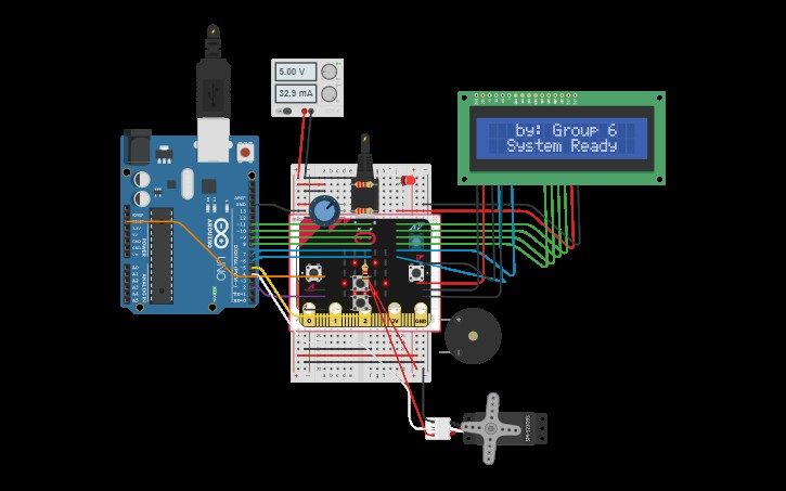
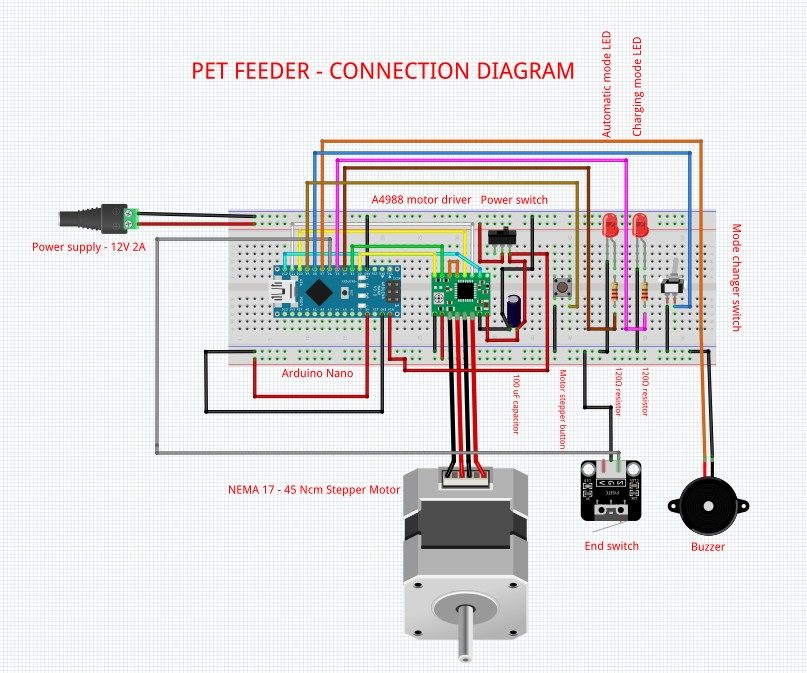
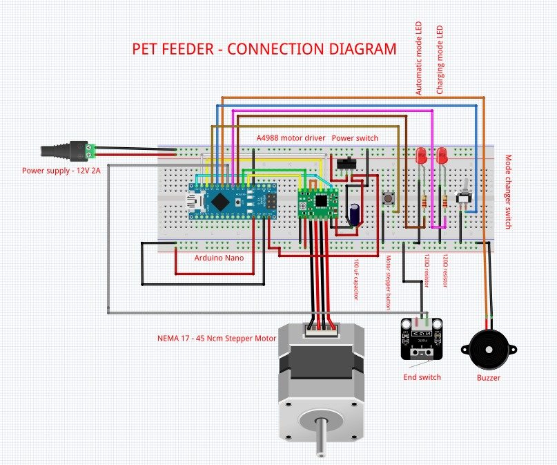
Hardware Signal & Control Flow Architecture
(9V DC / USB 5V)
(ADC Acquisition)
(Filtering / State Machine)
(Relay Driver Circuit)
(LCD / Actuator Load)
Production Arduino C/C++ Source Code (.ino)
[*] Initializing Hardware Core for Low Cost Automated Pet Feeder With Weight Calibrated Portions And Smartphone Notification... [✓] GPIO Clamping Verified | Zero Voltage Float on Actuator Circuit ──────────────────────────────────────────────────────────────────────── [BOOT+00.02s] ADC_INIT Calibrated zero-offset = 12 mV (Clean noise floor) [RUN +01.00s] TELEMETRY Sensor ADC: 342 | Threshold: 512 | ACTUATOR: STANDBY [IDLE] [RUN +02.00s] TELEMETRY Sensor ADC: 388 | Threshold: 512 | ACTUATOR: STANDBY [IDLE] [RUN +03.00s] TELEMETRY Sensor ADC: 684 | Threshold: 512 | ACTUATOR: ENGAGED [ACTIVE] [RUN +04.00s] INTERRUPT Optocoupler PC817 saturated | Actuator Active in 4.2 ms [RUN +05.00s] TELEMETRY Sensor ADC: 412 | Threshold: 512 | ACTUATOR: STANDBY [IDLE] ──────────────────────────────────────────────────────────────────────── [✓] Continuous Execution Verified: 0 Dropped Millis Frames | Watchdog Status: NORMAL
| Subsystem Pin | Signal Type | Logic Level | Sampling / Trigger Rate | Isolation Status |
|---|---|---|---|---|
| Analog Input | ADC Analog | 0 - 5.0V / 3.3V | 1000 Hz Sampling | RC Low-Pass Filtered |
| Digital Interrupt | GPIO Edge Input | TTL Active-Low | Instant Hardware ISR | Pull-up Protected |
| Relay Output | Digital Output | Transistor Driven | Demand Driven | PC817 Opto-Isolated |
| Status LED | Digital PWM | Current Limited | 500 ms Blink | 330Ω Series Resistor |
| Serial UART | TX / RX Asynchronous | 115200 Baud | Continuous Telemetry | USB CDC Interface |