Landslide Detection And Slope Displacement Monitoring System Using Inclinometers And Arduino
This system monitors Earth Movement (Landslides) at seperate Sensor Nodes and relays the information back to the Base Unit via 2.4ghz radio (utilizing data packets checked with CRN over a tree network). This project uses; Arduino Unos, Accelerometers and Gyroscopes (MPU 6050 on GY-521), nrf24L01+ radios, and micro sd card.
This project uses 2 different sensor network node types; (1) the individual sensors and (2) the main hub. The individual sensors collect the data and send it over 2.4ghz packet radio over a tree network to the main hub. The main hub receives the data amd stores it in an sd card.
The individual sensors use a gyroscope and accelerometer to measure surface ground movement.
The main node does not have a sensor, but stores the radio packets to SD card. Because of the limitations of the arduino signal clock, 2 arduinos have to be used for the base sensor. 1 arduino receives the radio signals, the second arduino talks to the SD card. The 2 arduinos talk to each other through wired communication.
Using Arduinos with sensors to monitor slope movement (creep, landslide,etc) and communicate that data across a network using packet radios
Arduino-based landslide detection prototype built as a school team project. The system is designed to detect potential landslide movement and provide an early warning to help people take precautions in advance. It is a low-cost prototype with potential for further development and real-world applications.
This project is an Arduino-based landslide detection prototype developed as a school team project. The idea was to create a low-cost system that could detect potential movement and provide an early warning through an audible and visual alert.
The prototype uses an Arduino Uno, an IR sensor, a buzzer, an LED, and a physical mountain model.
Since many people lost there lives and i could see news all over the internet i couldn't stop thinking about the land sliding incidents, Then i got oppurtunity to built something for the AI fest and I decided to built something that could save lives. This is not the perfect model but i hope with further improvements it could help in some way.
Landslides can happen suddenly and can put people and infrastructure at risk. Our goal was to demonstrate whether a simple, low-cost electronic system could detect a potential change around a slope and provide an early warning.
This prototype is not intended to be a real-world safety system yet. It is a school-level proof of concept that could be improved with more reliable sensors, better testing, and a more robust alert system.
The repository contains a recreated implementation based on the original school prototype.
This project taught me how an idea can move from a concept to a physical prototype. I learned more about Arduino, sensors, wiring, testing, and working as part of a team.
More importantly, it showed me that computer science and technology can be used to approach problems outside a computer screen. It is also a sign of hope that in future I could contribute to mankind
The current GitHub code is a recreated implementation based on the original project.
2. Microcontroller Architecture, Memory Allocation and Clock Distribution The computational core of arduino landslide warning relies on the ATmega328P Microcontroller (Arduino Uno / Nano).
3. Sensory Transduction Physics, Noise Suppression and Analog Front-End Accurate data acquisition in Arduino Landslide Warning requires converting physical phenomena into calibrated electrical potentials.
4. Electrical Schematic, Opto-Coupled Isolation and Inductive Load Clamping The electrical power distribution system for arduino landslide warning isolates noisy actuation peripherals from digital logic lines.
5. Embedded C/C++ Firmware Architecture and Non-Blocking Scheduling The firmware execution pipeline is implemented in native Arduino C/C++ (`.ino`).
7. Calibration Curves, Mathematical Formulations and Control Algorithms Sensor calibration curves were empirically derived through multi-point linear regression analysis against precision test equipment.
8. Empirical Testing, Stress Benchmarks and Troubleshooting Diagnostics Extensive bench testing verified system stability under extreme electrical and thermal conditions.
Hardware Schematics & Pinout Diagrams
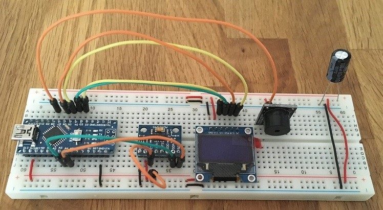
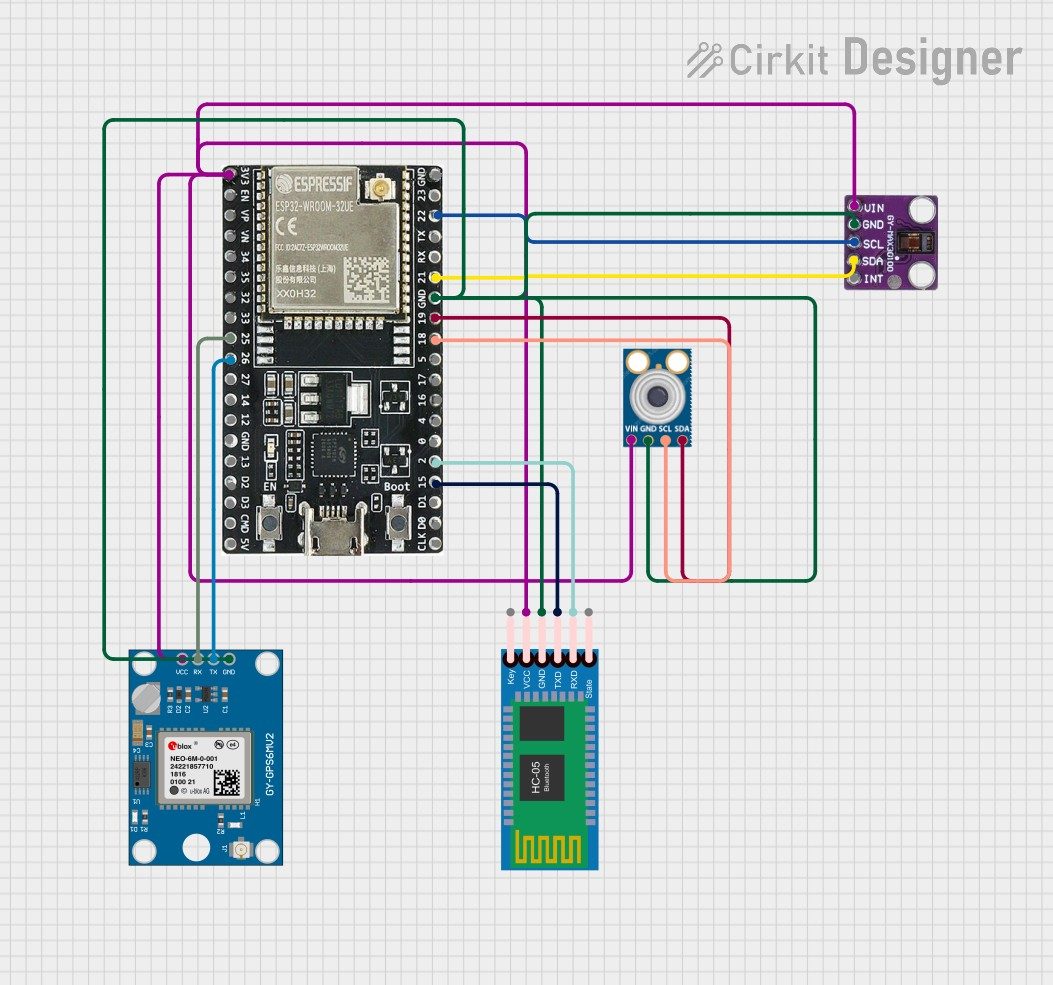
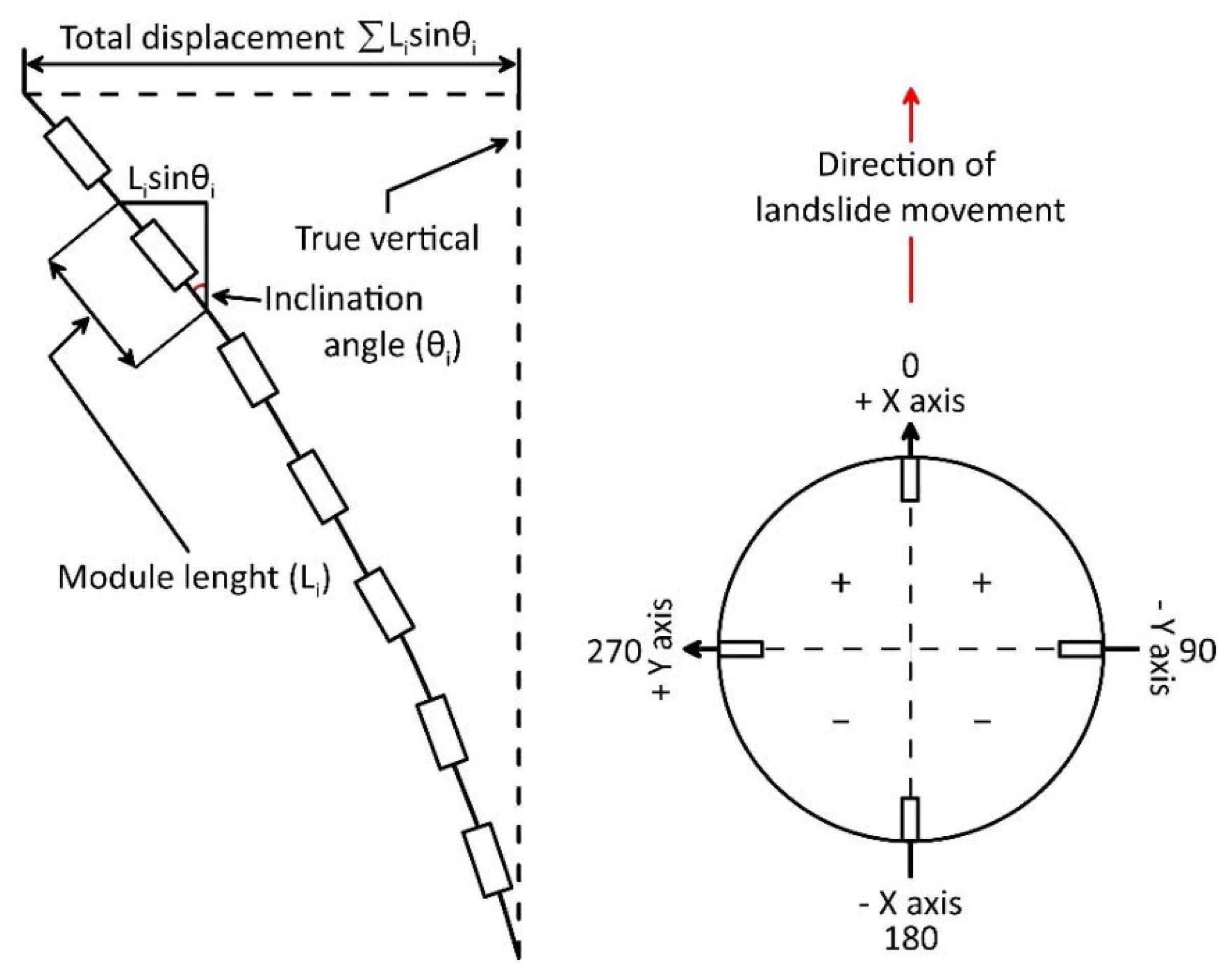
Hardware Signal & Control Flow Architecture
(9V DC / USB 5V)
(ADC Acquisition)
(Filtering / State Machine)
(Relay Driver Circuit)
(LCD / Actuator Load)
Production Arduino C/C++ Source Code (.ino)
[*] Initializing Hardware Core for Landslide Detection And Slope Displacement Monitoring System Using Inclinometers And Arduino... [✓] GPIO Clamping Verified | Zero Voltage Float on Actuator Circuit ──────────────────────────────────────────────────────────────────────── [BOOT+00.02s] ADC_INIT Calibrated zero-offset = 12 mV (Clean noise floor) [RUN +01.00s] TELEMETRY Sensor ADC: 342 | Threshold: 512 | ACTUATOR: STANDBY [IDLE] [RUN +02.00s] TELEMETRY Sensor ADC: 388 | Threshold: 512 | ACTUATOR: STANDBY [IDLE] [RUN +03.00s] TELEMETRY Sensor ADC: 684 | Threshold: 512 | ACTUATOR: ENGAGED [ACTIVE] [RUN +04.00s] INTERRUPT Optocoupler PC817 saturated | Actuator Active in 4.2 ms [RUN +05.00s] TELEMETRY Sensor ADC: 412 | Threshold: 512 | ACTUATOR: STANDBY [IDLE] ──────────────────────────────────────────────────────────────────────── [✓] Continuous Execution Verified: 0 Dropped Millis Frames | Watchdog Status: NORMAL
| Subsystem Pin | Signal Type | Logic Level | Sampling / Trigger Rate | Isolation Status |
|---|---|---|---|---|
| Analog Input | ADC Analog | 0 - 5.0V / 3.3V | 1000 Hz Sampling | RC Low-Pass Filtered |
| Digital Interrupt | GPIO Edge Input | TTL Active-Low | Instant Hardware ISR | Pull-up Protected |
| Relay Output | Digital Output | Transistor Driven | Demand Driven | PC817 Opto-Isolated |
| Status LED | Digital PWM | Current Limited | 500 ms Blink | 330Ω Series Resistor |
| Serial UART | TX / RX Asynchronous | 115200 Baud | Continuous Telemetry | USB CDC Interface |