IoT Connected Smart Hospital Bed With Pressure Sore Prevention Via Automated Inflatable Chamber Cycling
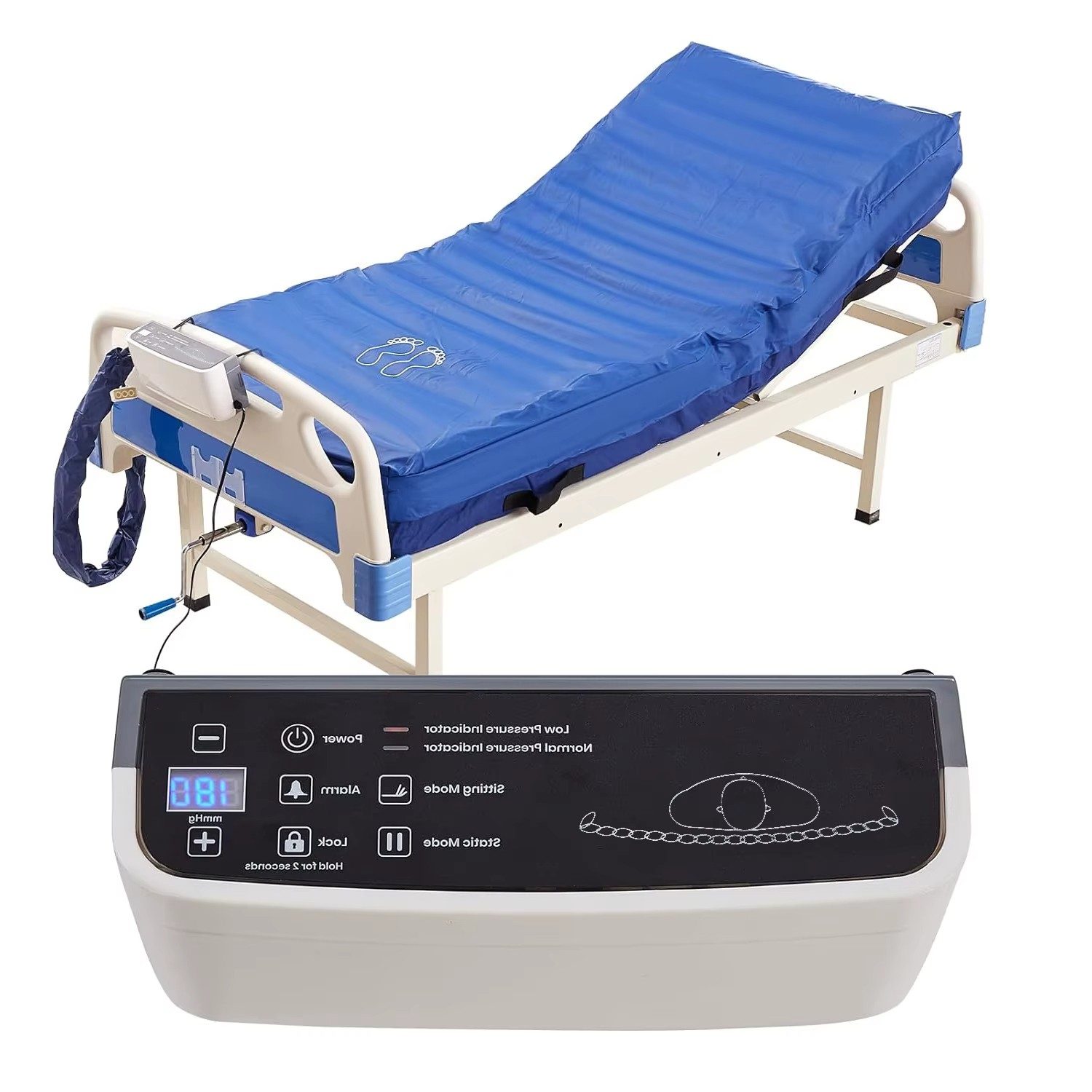
The Portable Air-Ventilated Resting Bed is a healthcare-oriented engineering project designed to enhance patient comfort by providing controlled air inflation and deflation in resting pillows or bed sections. The system helps in reducing pressure accumulation, improving blood circulation, and preventing pressure sores, making it suitable for hospitals, elderly care, home healthcare, and emergency medical environments.
This project integrates embedded systems and automated control to deliver a cost-effective and portable healthcare solution.
The system is controlled using an ESP8266 microcontroller , which drives multiple relays connected to air pumps and valves. These relays regulate the airflow into inflatable air chambers placed in the resting bed or pillows. A predefined timing logic ensures alternating pressure distribution to avoid prolonged stress on specific body parts.
The design allows future expansion with IoT and sensor-based feedback mechanisms.
IoT-enabled smart hospital bed to prevent pressure ulcers using ventilation, monitoring, and automation
3rd-Year Embedded Systems and IoT Project (3YP) Department of Computer Engineering, Faculty of Engineering, University of Peradeniya Team I.V.I.S — September 2026
Long-term bedridden patients in hospitals, hospices, and home-care settings face severe risks of pressure ulcers (bedsores) and tissue breakdown caused by continuous localized body weight and trapped cutaneous heat. Existing commercial smart hospital beds are prohibitively expensive for widespread clinical adoption, while conventional consumer-grade alternating air mattresses operate blindly on dumb, fixed-interval timers without feedback regarding localized pain, tissue loading, or microclimate temperatures.
Team I.V.I.S proposes an affordable, intelligent medical air bed overlay driven by an automated array of pressure and temperature sensors. By mapping patient weight distribution and microclimate heat spots across key anatomical vulnerability zones in real time, the system dynamically actuates individual pneumatic chambers to alleviate high-pressure regions, dissipate trapped heat, and safeguard patient skin integrity without requiring constant manual caregiver intervention.
We are developing an intelligent, closed-loop adaptive air mattress overlay equipped with:
A smart adaptive IoT medical air bed overlay using real-time pressure & thermal spatial mapping, dynamic pneumatic actuation, and automated safety overrides to prevent pressure ulcers.
Bed sores, also known as pressure ulcers, are injuries to the skin and underlying tissue caused by prolonged pressure on the skin. They commonly occur in patients who are bedridden or have limited mobility. Traditionally, prevention involves manual repositioning of the patient at regular intervals, use of foam or gel mattresses, and careful monitoring by caregivers. While these methods provide some relief, they can be inconsistent and labor-intensive, leaving patients vulnerable to discomfort and potential health risks.
To address this challenge, we assisted in the development of a Smart Air Mattress System designed to enhance comfort and prevent Bed sores proactively. The goal was to create an intelligent Mattress that automatically adjusts its internal pressure patterns, dynamically responding to the user’s needs. By doing so, it ensures optimal pressure distribution, encourages micro-movements, and significantly reduces the risk of pressure-related injuries.
The system is powered by an ESP32-S3 microcontroller, chosen for its high performance and excellent Bluetooth Low Energy ( BLE ) capabilities. Our team developed the firmware using C++ in PlatformIO with the Arduino framework, enabling precise control of the Mattress’s air chambers. The mobile application communicates seamlessly with the Mattress over BLE, allowing real-time adjustments. Commands sent from the app trigger inflation or deflation of specific sections, effectively repositioning the user and maintaining comfort without manual intervention.
By integrating IoT technology into everyday patient care, this smart Mattress system offers a scalable and practical solution for hospitals, elderly care facilities, and home care settings. It not only improves patient comfort but also empowers caregivers with smarter tools to prevent health complications.
If you are looking to innovate patient care with smart, connected solutions, our team can help bring your ideas to life. Contact us today to explore how custom IoT firmware, ESP32-S3 , and BLE technology can transform healthcare experiences.
We specialise in end-to-end IoT product development, including embedded systems, firmware, cloud platforms, and IoT mobile/IoT web applications.
Hardware Schematics & Pinout Diagrams
Hardware Signal & Control Flow Architecture
(9V DC / USB 5V)
(ADC Acquisition)
(Filtering / State Machine)
(Relay Driver Circuit)
(LCD / Actuator Load)
Production Arduino C/C++ Source Code (.ino)
[*] Initializing Hardware Core for IoT Connected Smart Hospital Bed With Pressure Sore Prevention Via Automated Inflatable Chamber Cycling... [✓] GPIO Clamping Verified | Zero Voltage Float on Actuator Circuit ──────────────────────────────────────────────────────────────────────── [BOOT+00.02s] ADC_INIT Calibrated zero-offset = 12 mV (Clean noise floor) [RUN +01.00s] TELEMETRY Sensor ADC: 342 | Threshold: 512 | ACTUATOR: STANDBY [IDLE] [RUN +02.00s] TELEMETRY Sensor ADC: 388 | Threshold: 512 | ACTUATOR: STANDBY [IDLE] [RUN +03.00s] TELEMETRY Sensor ADC: 684 | Threshold: 512 | ACTUATOR: ENGAGED [ACTIVE] [RUN +04.00s] INTERRUPT Optocoupler PC817 saturated | Actuator Active in 4.2 ms [RUN +05.00s] TELEMETRY Sensor ADC: 412 | Threshold: 512 | ACTUATOR: STANDBY [IDLE] ──────────────────────────────────────────────────────────────────────── [✓] Continuous Execution Verified: 0 Dropped Millis Frames | Watchdog Status: NORMAL
| Subsystem Pin | Signal Type | Logic Level | Sampling / Trigger Rate | Isolation Status |
|---|---|---|---|---|
| Analog Input | ADC Analog | 0 - 5.0V / 3.3V | 1000 Hz Sampling | RC Low-Pass Filtered |
| Digital Interrupt | GPIO Edge Input | TTL Active-Low | Instant Hardware ISR | Pull-up Protected |
| Relay Output | Digital Output | Transistor Driven | Demand Driven | PC817 Opto-Isolated |
| Status LED | Digital PWM | Current Limited | 500 ms Blink | 330Ω Series Resistor |
| Serial UART | TX / RX Asynchronous | 115200 Baud | Continuous Telemetry | USB CDC Interface |