IoT Based Residential Water Usage Profiler With Sub Pipe Leakage Detection And Valve Cut Off
HydroLeak is an IoT-based Smart Water Pipeline Leakage Detection and Management System developed to reduce water wastage through real-time monitoring and automated leak detection. The system uses an ESP32 microcontroller, water flow sensor, GPS module, relay, buzzer, and the Blynk IoT platform to continuously monitor water flow in pipelines.
When abnormal water flow indicating a leakage is detected, HydroLeak automatically turns off the water motor, activates a buzzer, sends an email notification, and provides the GPS location of the leakage. The solution is suitable for residential, agricultural, and municipal water distribution systems, promoting efficient water management and conservation.
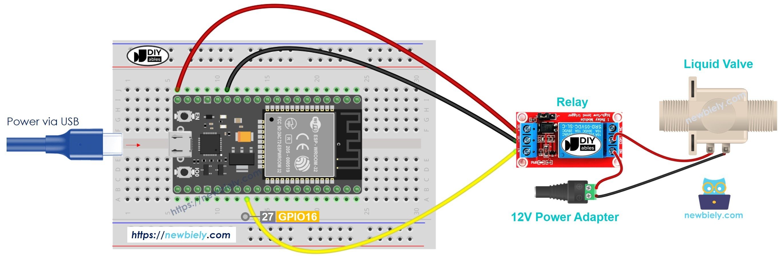
The above circuit diagram illustrates the hardware connections between the ESP32, Water Flow Sensor, GPS Module, Relay Module, Water Pump, and Buzzer used in the HydroLeak system.
HydroLeak – IoT-based Smart Water Pipeline Leakage Detection System This repository contains the Arduino code and hardware design for HydroLeak, a project that monitors water pipelines in real time, detects leakages using sensors, and sends alerts via Blynk and email to reduce water wastage and improve maintenance efficiency.
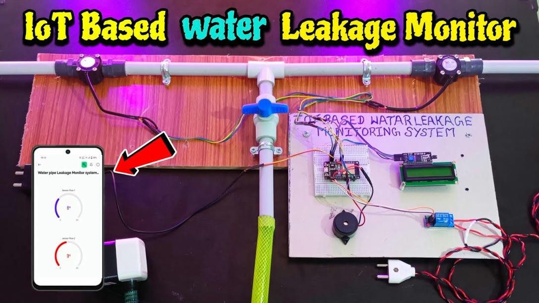
This project implements an IoT-based real-time pipe flow and leak monitoring prototype using NodeMCU ESP8266 , water flow sensors , LED indicators , and an active buzzer . It detects anomalies such as leaks, no-flow conditions, and transient states while providing a live web dashboard for monitoring.
🧾 The Real-Time Pipe Flow and Leak Monitoring System is designed to detect abnormal flow patterns in pipelines using IoT-enabled components. It continuously measures water flow at two points to identify leaks, no-flow conditions, and transient flow states. Data is transmitted wirelessly and displayed through an HTML/JavaScript-based dashboard hosted on the ESP8266.
This system is beneficial for water distribution , industrial fluid transport , and environmental management , making pipeline monitoring more efficient and sustainable.
🚨 Water wastage due to hidden leaks, inefficient monitoring systems, and illegal pipe tampering is a major issue—especially in Sabah, where illegal tapping causes up to 60% revenue loss . Manual monitoring often fails to detect leaks early.
📘 The system uses IoT sensors, wireless communication, and a web interface to detect pipeline anomalies. Components include:
An IoT-based real-time pipe flow and leak monitoring system built using ESP8266, dual water flow sensors, buzzer, LED indicators, and a web dashboard for live anomaly detection. Developed using Arduino IDE.
Hardware Schematics & Pinout Diagrams
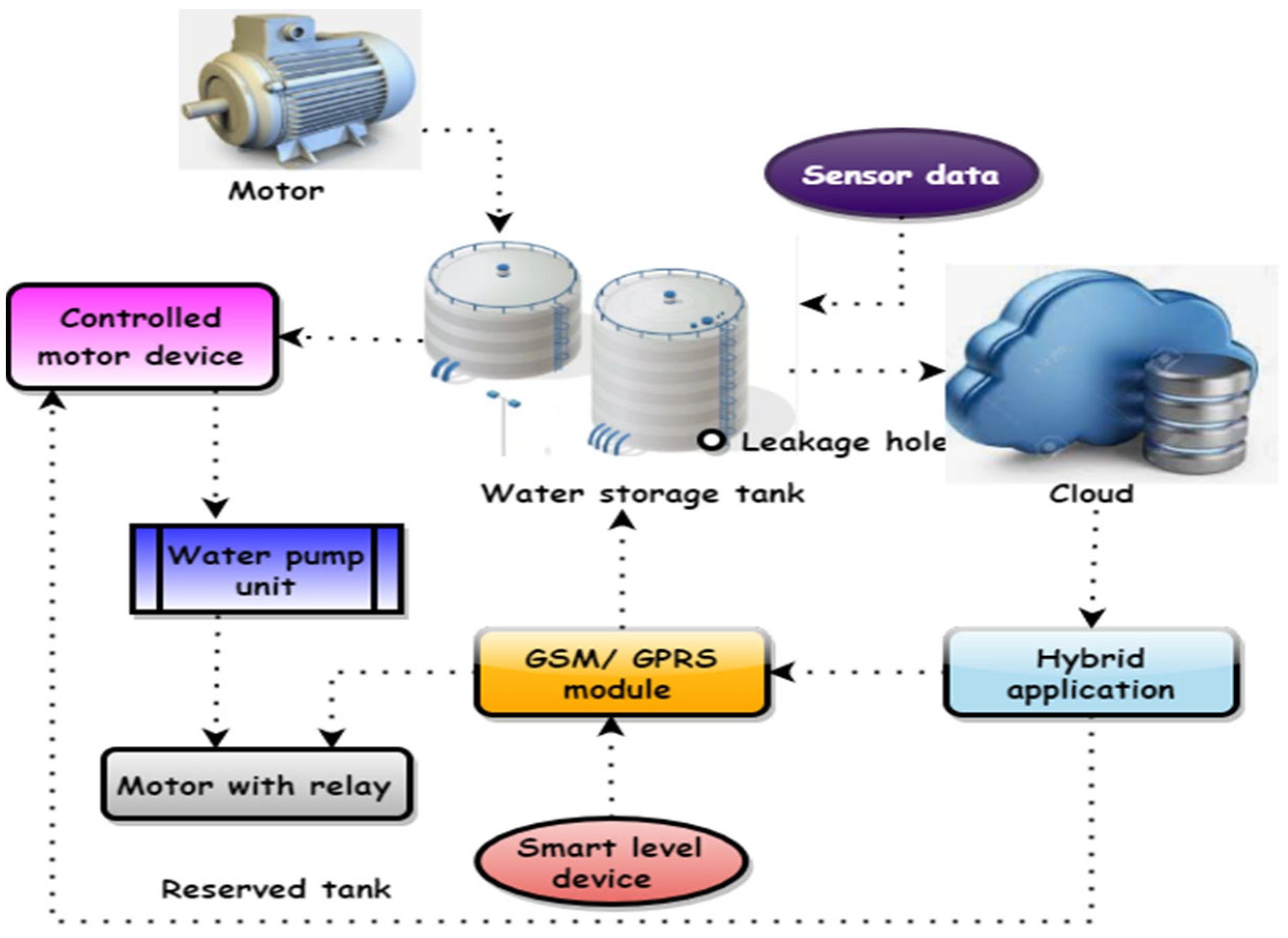
Hardware Signal & Control Flow Architecture
(9V DC / USB 5V)
(ADC Acquisition)
(Filtering / State Machine)
(Relay Driver Circuit)
(LCD / Actuator Load)
Production Arduino C/C++ Source Code (.ino)
[*] Initializing Hardware Core for IoT Based Residential Water Usage Profiler With Sub Pipe Leakage Detection And Valve Cut Off... [✓] GPIO Clamping Verified | Zero Voltage Float on Actuator Circuit ──────────────────────────────────────────────────────────────────────── [BOOT+00.02s] ADC_INIT Calibrated zero-offset = 12 mV (Clean noise floor) [RUN +01.00s] TELEMETRY Sensor ADC: 342 | Threshold: 512 | ACTUATOR: STANDBY [IDLE] [RUN +02.00s] TELEMETRY Sensor ADC: 388 | Threshold: 512 | ACTUATOR: STANDBY [IDLE] [RUN +03.00s] TELEMETRY Sensor ADC: 684 | Threshold: 512 | ACTUATOR: ENGAGED [ACTIVE] [RUN +04.00s] INTERRUPT Optocoupler PC817 saturated | Actuator Active in 4.2 ms [RUN +05.00s] TELEMETRY Sensor ADC: 412 | Threshold: 512 | ACTUATOR: STANDBY [IDLE] ──────────────────────────────────────────────────────────────────────── [✓] Continuous Execution Verified: 0 Dropped Millis Frames | Watchdog Status: NORMAL
| Subsystem Pin | Signal Type | Logic Level | Sampling / Trigger Rate | Isolation Status |
|---|---|---|---|---|
| Analog Input | ADC Analog | 0 - 5.0V / 3.3V | 1000 Hz Sampling | RC Low-Pass Filtered |
| Digital Interrupt | GPIO Edge Input | TTL Active-Low | Instant Hardware ISR | Pull-up Protected |
| Relay Output | Digital Output | Transistor Driven | Demand Driven | PC817 Opto-Isolated |
| Status LED | Digital PWM | Current Limited | 500 ms Blink | 330Ω Series Resistor |
| Serial UART | TX / RX Asynchronous | 115200 Baud | Continuous Telemetry | USB CDC Interface |