IoT Based Real Time Phase Imbalance Monitor And Alerting System For Distribution Feeders
IOT 3 Phase Transformer Load monitoring- In this Tutorial, you will learn how to make a 3 phase transformer load monitoring system using Arduino, Nodemcu esp8266 wifi module and Blynk application. With the help of the Nodemcu module and Blynk application the load on each phase “Red, Yellow, and Blue” can be monitored in real-time from anywhere around the world using your cell phone.
This is the 2 nd version of the 3 phase transformer load monitoring system based on IoT “Internet of Things”, while in the first version;
I designed an application in vb.net and used this application to monitor all the three phases of the 3 phase transformer prototype model. The transformer wiring, soldering, the acs712 current sensors connections, soldering, and interfacing is already explained in very detail. For the best understanding, I recommend you should watch my first tutorial on 3 phase transformer load monitoring system and then you can resume from here.
Please Note: these are affiliate links. I may make a commission if you buy the components through these links. I would appreciate your support in this way!
This is the circuit diagram which I used in version 1, which I have already explained in very detailed and the link is given above. As you can see in the Circuit Diagram above three acs712 current sensors are connected with the analog pins A1, A2, and A3.
The three bulbs connected with the Red, Yellow, and Blue Phases. Arduino calculates the load and then send the values to the computer application.
While this is the modified circuit diagram, in which Nodemcu is used. The 5v regulated power supply is based on the lm7805 voltage regulator. Two 470uf capacitors are connected at the input and output of the regulator. A 330-ohm resistor connected in series with a 2.5v led. This is a current limiting resistor, while J1 is the dc female power Jack, this is where we can connect a 12v adaptor or battery. The output of the 7805 Regulator is connected with the Vin pin of the Nodemcu module while the ground is connected with the ground. Connect the TX pin of the Nodemcu module with the RX pin of the Arduino and connect the RX pin of the Nodemcu module with the TX pin of the Arduino and also make sure you connect the ground pin of the Nodemcu module with the ground pin of the Arduino. So this is the only modification that I made in the 2 nd version.
As you can see all the connections are exactly the same as explained in version 1. The Red, Yellow, Blue, and Neutral wires are connected with the PVC Strip connector.
As you can see I am using the same connections, the only modification that I made is the addition of the Nodemcu module and a 5v regulated power supply. This time I am power up the Arduino and Nodemcu module using a 12v adaptor.
This is the 5v regulated power supply as explained in the circuit diagram. The output of the regulated power supply which is 5v is connected with the Vin pin of the Nodemcu module and the ground of the power supply is connected with the ground of the Nodemcu module. The TX and RX pins of the Nodemcu module are connected with the RX and TX pins of the Arduino. the ground of the Nodemcu module is connected with the ground of the Arduino, while rest of the connections are exactly the same as explained in version 1 of the 3 phase transformer load monitoring system using a Computer application. Now let’s make a blynk application.
For the detailed explanation and Step by Step making of the Blynk application watch Video Tutorial given at the end of this Article.
This Project is based on two Programs, one Program is written for the Arduino Uno while the other Program is written for the Nodemcu ESP8266 Wifi Module. The Arduino Program as explained in my Previous Tutorial remains the same. Link to the Version1 of the 3 phase transformer load monitoring system is given above.
Before you start the programming for the IOT 3 Phase Transformer Load Monitoring System, first of all, make sure that you download all the necessary libraries and you install the Nodemcu board and you also install a driver for the USB UART.
Load balancing of a 3 phase transformer- In this Tutorial, you will learn how to make a 3 phase transformer consumers load monitoring and load balancing or load shifting project using Arduino, 433Mhz Radio Frequency Transmitter and Receivers.
This application will be used for monitoring all the three phases Red, Yellow, and Blue in Real-time.
While with the help of this application any consumer can be connected with any of the 3 phases. Let me show you this practically. Let’s connect consumer 2 with the Yellow phase as you can see the bulb is turned ON, and you can also see an increase in the value.
You can see the bulb is turned on and the value is further increased. As you can see currently the load on the yellow phase is more than the red phase and blue phase. Now to reduce load on the yellow phase we can shift consumer 2 or consumer3 on any other phase. let’s connect consumer 3 with the red phase. A
As you can see the load on the yellow phase is reduced, this way we can do the load balancing. In case of any emergency a consumer can be disconnected.
As you can see the value on the Blue Phase is increased. let’s connect consumer 2 with the blue phase as well.
You can see the value is further increased. Now the load on the blue phase is greater than the other two phases, to reduce load on the blue phase we can shift the consumer load on any other phase. All these consumers are wirelessly controlled using 433Mhz Radiofrequency Transmitters and receivers. One transmitter is used to send commands to 3 receiver modules.
While in the first version; I designed an application in vb.net and used this application to monitor all the three phases of the 3 phase transformer prototype model.
In the second version , I used the Blynk application for monitoring all the three phases in real-time from anywhere around the world using a cell phone, Arduino, and Nodemcu esp8266 wifi module.
IOT 3 Phase Transformer Load Monitoring using Nodemcu ESP266 and Arduino: Version 2
As this is the version 3 of the 3 phase transformer load monitoring and load balancing system, this project is around 70% based on the version1, as I will be using the same connections and the same computer application for monitoring all the three phases.
As in this tutorial, I will only explain the modifications which are
Cautions: This Project makes use of the 220/230Vac, do not touch any wires while the transformers are turned ON may result in a heavy shock or it can be lethal.
While this is the modified circuit diagram used in Version2 of the 3 phase transformer load monitoring system using Nodemcu esp8266 wifi module and Arduino. Regulated power supply is based on the lm7805 voltage regulator.
While this is the final modified circuit diagram in which three consumers are added. The consumer supply is controlled using a transmitter which will be connected with the computer application. Let’s start with the transmitter side, as you can see the 433Mhz RF transmitter data pin is connected with the Arduino’s pin number 12 while the transmitter 5v and GND pins are connected with the Arduino’s 5v and Ground.
Hardware Schematics & Pinout Diagrams
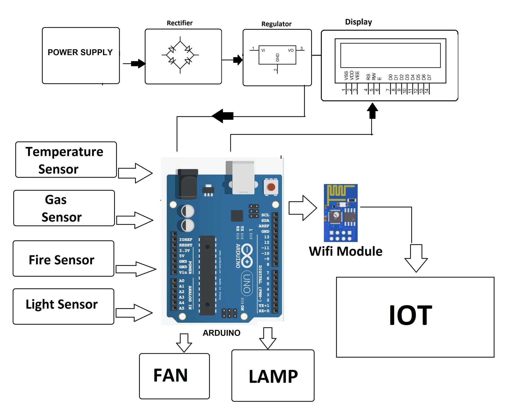
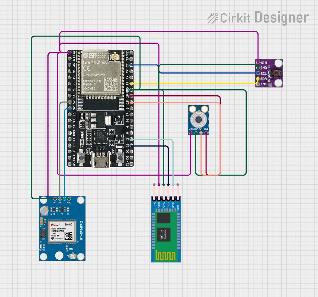
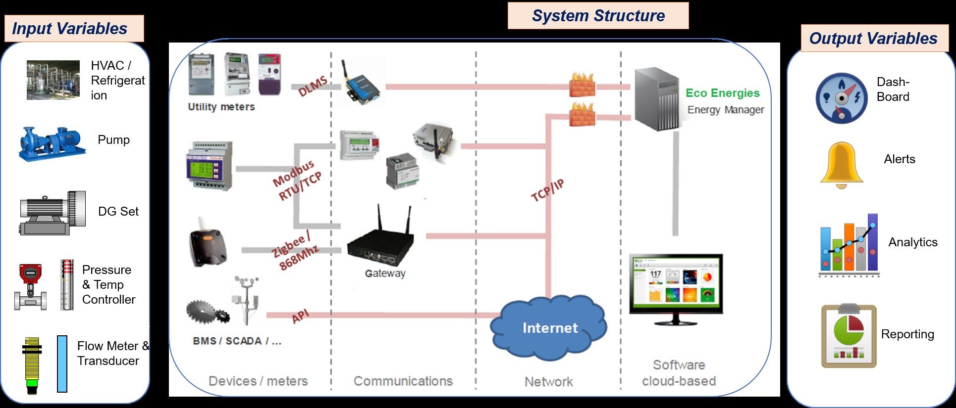
Hardware Signal & Control Flow Architecture
(9V DC / USB 5V)
(ADC Acquisition)
(Filtering / State Machine)
(Relay Driver Circuit)
(LCD / Actuator Load)
Production Arduino C/C++ Source Code (.ino)
[*] Initializing Hardware Core for IoT Based Real Time Phase Imbalance Monitor And Alerting System For Distribution Feeders... [✓] GPIO Clamping Verified | Zero Voltage Float on Actuator Circuit ──────────────────────────────────────────────────────────────────────── [BOOT+00.02s] ADC_INIT Calibrated zero-offset = 12 mV (Clean noise floor) [RUN +01.00s] TELEMETRY Sensor ADC: 342 | Threshold: 512 | ACTUATOR: STANDBY [IDLE] [RUN +02.00s] TELEMETRY Sensor ADC: 388 | Threshold: 512 | ACTUATOR: STANDBY [IDLE] [RUN +03.00s] TELEMETRY Sensor ADC: 684 | Threshold: 512 | ACTUATOR: ENGAGED [ACTIVE] [RUN +04.00s] INTERRUPT Optocoupler PC817 saturated | Actuator Active in 4.2 ms [RUN +05.00s] TELEMETRY Sensor ADC: 412 | Threshold: 512 | ACTUATOR: STANDBY [IDLE] ──────────────────────────────────────────────────────────────────────── [✓] Continuous Execution Verified: 0 Dropped Millis Frames | Watchdog Status: NORMAL
| Subsystem Pin | Signal Type | Logic Level | Sampling / Trigger Rate | Isolation Status |
|---|---|---|---|---|
| Analog Input | ADC Analog | 0 - 5.0V / 3.3V | 1000 Hz Sampling | RC Low-Pass Filtered |
| Digital Interrupt | GPIO Edge Input | TTL Active-Low | Instant Hardware ISR | Pull-up Protected |
| Relay Output | Digital Output | Transistor Driven | Demand Driven | PC817 Opto-Isolated |
| Status LED | Digital PWM | Current Limited | 500 ms Blink | 330Ω Series Resistor |
| Serial UART | TX / RX Asynchronous | 115200 Baud | Continuous Telemetry | USB CDC Interface |