Intelligent Parking Garage Air Ventilation Fan Speed Optimizer Based On Carbon Monoxide Levels
The Smart Ventilation System is an intelligent environmental control project designed to monitor and regulate air quality, temperature, and airflow automatically. This system ensures proper ventilation in indoor spaces such as homes, gyms, classrooms, and industrial areas.
It uses sensors and a microcontroller to detect environmental conditions and control fans or vents accordingly.
void loop { float temp = dht.readTemperature; float hum = dht.readHumidity; int gasValue = analogRead(GAS_SENSOR);
// check sensor error if (isnan(temp) || isnan(hum)) { Serial.println("DHT sensor error!"); delay(2000); return; }
// ventilation condition if (temp > 47 || gasValue > 450) { digitalWrite(RELAY,LOW); // fan ON Serial.println("Fan Status: ON (Danger)"); } else { digitalWrite(RELAY, HIGH ); // fan OFF Serial.println("Fan Status: OFF (Normal)"); }
Automated ventilation control system using Arduino, ESP32, and IoT-based sensor feedback
Ensuring air quality and safety is essential, especially in enclosed spaces where gas buildup can occur. In this project, we'll create an automatic gas detection and ventilation system using Arduino , an MQ2 gas sensor , and a 12V fan controlled via an IRF540N MOSFET . This setup can detect gases like methane, propane, and smoke, automatically activating a fan to ventilate the area if gas levels exceed a certain threshold. This guide is perfect for applications in garages, workshops, or even basements, where monitoring air quality is a priority.
The system works by reading the gas concentration from the MQ2 gas sensor and using the Arduino to monitor if levels go beyond a set threshold. When gas levels rise, the Arduino triggers the fan via an IRF540N MOSFET , providing a quick and efficient way to ventilate the space. For a deeper understanding of this process, you can refer to our article on the M Q 2 G a s S e n s o r w i t h A r d u i n o a n d L C D for additional setup insights.
For controlling the fan, we're using an IRF540N MOSFET instead of a relay module, which makes the circuit more efficient and can handle higher currents easily. If you’re new to working with MOSFETs in Arduino projects, you can check out our U l t i m a t e G u i d e t o I R F 5 4 0 N f o r A r d u i n o U s e r s to understand how to wire and control it.
The circuit diagram of the Automatic Gas Detection and Ventilation System with Arduino is shown below.
This gas detection and ventilation control system has a wide range of applications in home and industrial settings, such as:
This project also makes use of a PID Controller approach, commonly used in temperature control projects. To see how Arduino can be used as a PID controller, check out our U l t i m a t e G u i d e t o U s i n g A r d u i n o a s a P I D C o n t r o l l e r and our article on B u i l d i n g a P I D - C o n t r o l l e d T e m p e r a t u r e S y s t e m .
See how the automatic gas detection and ventilation control system with Arduino, MQ2 Sensor, and IRF540N MOSFET works.
With just a few components, you can build an effective gas detection and ventilation system. By integrating an MQ2 sensor and IRF540N MOSFET , this setup provides real-time response to changes in gas levels, ensuring safety in any workspace or home environment.
For more on PID-based control, you may also enjoy our tutorial on the A r d u i n o P I D C o n t r o l l e r f o r T e m p e r a t u r e C o n t r o l , which dives into managing real-time variables using Arduino. This knowledge will be invaluable in creating automated systems for home, lab, or garage environments.
An ESP32-based smart ventilation system that monitors indoor air quality and automatically adjusts fan speed using a PID controller.
The system was developed as part of my bachelor's thesis. Its purpose is to maintain the CO2 concentration around a reference value of 1000 ppm by continuously adjusting the ventilation level.
The MH-Z19C sensor measures the CO2 concentration inside the test enclosure and sends the value to the ESP32 through UART communication.
The ESP32 calculates the control error as the difference between the measured CO2 concentration and the 1000 ppm setpoint. The PID controller then determines the required fan command.
The resulting command is converted into a PWM signal and applied to the fan through the L298N motor driver.
When the CO2 concentration rises above the setpoint, the fan speed increases. As the concentration approaches the reference value, the fan speed gradually decreases.
The initial controller parameters were calculated using the Internal Model Control method and were later adjusted experimentally on the physical setup.
During testing, the fan did not start reliably for PWM commands below approximately 24%.
To compensate for this behavior, every non-zero PID command is remapped from the logical range of 0-100% to the physical PWM range of 24-100%.
This ensures that the fan receives enough power to start whenever ventilation is required.
The Adafruit and DHT libraries can be installed using the Arduino IDE Library Manager. Wire and HardwareSerial are included with the ESP32 Arduino core.
The logged data can be saved and later used for plotting and performance analysis.
The system was tested inside a small enclosure with an approximate volume of 0.008 m³.
A reduced test volume was used to observe changes in CO2 concentration over a shorter period and to validate the controller under controlled conditions.
The identified first-order process model had the following approximate parameters:
Experimental tests showed that the system was able to reduce the CO2 concentration from approximately 1500-1800 ppm toward the 1000 ppm setpoint.
The controller produced a stable response without significant oscillations and gradually reduced the fan command as the CO2 concentration approached the reference value.
Bachelor's thesis project developed at the Faculty of Automatic Control and Computer Science , National University of Science and Technology POLITEHNICA Bucharest .
In this tutorial, we are going to learn how to turn on/off a fan using Arduino. Controlling the fan's speed will be presented in another tutorial.
The voltage of the DC power supply should be equal to the voltage specified by the fan. In this tutorial, we will use 12VDC and 5VDC fans.
To turn on/off a fan, we need to use a relay in between Arduino and fan. Arduino can turn on/off the fan via the relay. If you do not know about relay (pinout, how it works, how to program ...), learn about relay in the Arduino - Relay tutorial
Simply add a Proto Screw Terminal Block Shield or a Screw Shield V2 to the Arduino. See the diagram below for the screw shield version.
The below code repeatedly turns the fan ON in five seconds and OFF in five seconds,
Hardware Schematics & Pinout Diagrams
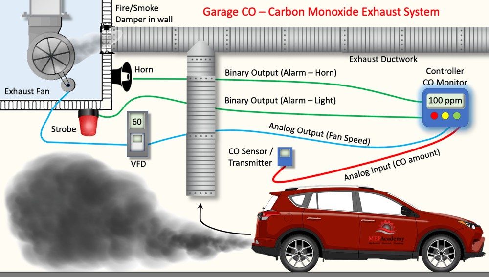
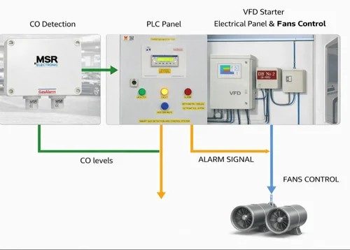
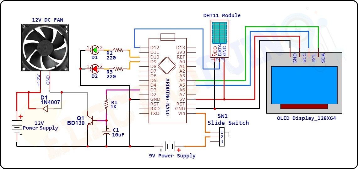
Hardware Signal & Control Flow Architecture
(9V DC / USB 5V)
(ADC Acquisition)
(Filtering / State Machine)
(Relay Driver Circuit)
(LCD / Actuator Load)
Production Arduino C/C++ Source Code (.ino)
[*] Initializing Hardware Core for Intelligent Parking Garage Air Ventilation Fan Speed Optimizer Based On Carbon Monoxide Levels... [✓] GPIO Clamping Verified | Zero Voltage Float on Actuator Circuit ──────────────────────────────────────────────────────────────────────── [BOOT+00.02s] ADC_INIT Calibrated zero-offset = 12 mV (Clean noise floor) [RUN +01.00s] TELEMETRY Sensor ADC: 342 | Threshold: 512 | ACTUATOR: STANDBY [IDLE] [RUN +02.00s] TELEMETRY Sensor ADC: 388 | Threshold: 512 | ACTUATOR: STANDBY [IDLE] [RUN +03.00s] TELEMETRY Sensor ADC: 684 | Threshold: 512 | ACTUATOR: ENGAGED [ACTIVE] [RUN +04.00s] INTERRUPT Optocoupler PC817 saturated | Actuator Active in 4.2 ms [RUN +05.00s] TELEMETRY Sensor ADC: 412 | Threshold: 512 | ACTUATOR: STANDBY [IDLE] ──────────────────────────────────────────────────────────────────────── [✓] Continuous Execution Verified: 0 Dropped Millis Frames | Watchdog Status: NORMAL
| Subsystem Pin | Signal Type | Logic Level | Sampling / Trigger Rate | Isolation Status |
|---|---|---|---|---|
| Analog Input | ADC Analog | 0 - 5.0V / 3.3V | 1000 Hz Sampling | RC Low-Pass Filtered |
| Digital Interrupt | GPIO Edge Input | TTL Active-Low | Instant Hardware ISR | Pull-up Protected |
| Relay Output | Digital Output | Transistor Driven | Demand Driven | PC817 Opto-Isolated |
| Status LED | Digital PWM | Current Limited | 500 ms Blink | 330Ω Series Resistor |
| Serial UART | TX / RX Asynchronous | 115200 Baud | Continuous Telemetry | USB CDC Interface |