Intelligent Indoor Air Purifier With Particle Counter Trigger And Hepa Filter Lifespan Calculation
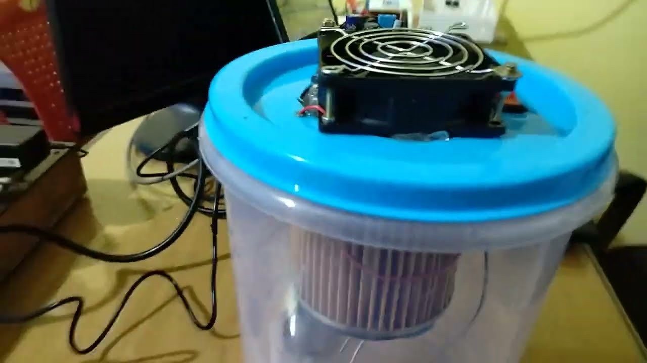
A low-cost DIY Smart Air Purifier that automatically adjusts fan speed based on real-time PM 2.5 concentration. The purifier uses a HEPA filter with a DC fan mounted on top and is designed to provide adaptive air cleaning for indoor environments.
This project includes both the hardware setup and Arduino-based control code , and is intended to be fully open-source for anyone to replicate or improve.
Real-Time Monitoring – Continuously monitors air quality using a PM 2.5 sensor. Automatic Fan Control – Adjusts fan speed dynamically according to PM 2.5 levels. Energy Efficient – Runs at lower speeds when air quality is good, saving power. HEPA Filtration – Effective particle removal for healthier indoor air. Open Source – Hardware design, circuit, and code freely available.
PM 2.5 Sensor - Sensirion's SEN50 Link HEPA Filter - 20cm diameter, 29cm height(Standard MI air purifier Filter) Link Power Supply - 12V 2amp DC power supply Link DC/AC Fan - 120mm*120mm, 12V DC Fan Link Microcontroller - Arduino Nano Link Motor Driver - L298N Motor Driver Link Display - 0.96inch OLED display Link
The current design supports three Sensirion models : SEN50, SEN54, and SEN55 . All of them share the same physical footprint, making them interchangeable in this setup.
Current design files support both 0.96-inch and 1.3-inch OLED displays. Please note that the pin locations for VCC and GND may vary depending on the display module, so always check the OLED pinout before connecting it to the circuit.
Both 2-pin and 3-pin DC fans can be used in this project. For controlling a 2-pin DC fan, we used an L298N motor driver module since it was readily available. Other methods, like MOSFET transistors, can also be used.
For 3-pin PWM fans , the 12V supply can be connected directly to the fan while the PWM control signal is driven from the Arduino Nano. This approach simplifies the circuit design since no external motor driver is required.
⚠️ However, PWM fans are generally more expensive than standard 2-pin fans, which can increase the overall cost of the project.
3D Parts There are 3 parts in the model. Top(Cover) , Middle(Hardware mounting) , and the Bottom part(Hepa Mount)
The top cover includes a slot for the OLED display, which can be secured on the designated pads using M2 screws (1–2 screws are sufficient). The other components—such as the SEN50 PM 2.5 sensor, L298N motor driver, Arduino Nano, and fan—should be installed at the positions indicated below. While installing, make sure the top cover matches the holes created for the SEN50 sensor and the landing legs on the cover match with holes on the middle part. Lastly, the bottom HEPA filter cover should be added to the middle part by the M2 screw through the allocated holes.
Air Sense is a smart IoT air purifier that monitors indoor air quality in real time and automatically removes harmful pollutants using intelligent sensing, cloud connectivity, and HEPA filtration.
The air we breathe indoors can often contain dust, pollutants, allergens, and microscopic particles that go unnoticed but can affect our health over time. While commercial air purifiers are becoming increasingly common, they are often expensive , difficult to customize, and provide little insight into the quality of the air around us.
To address this, I created AirSense —a smart DIY air purifier that combines air purification, environmental monitoring, and cloud connectivity into a single intelligent system. Rather than simply filtering air, AirSense continuously measures indoor air quality and provides real-time information about the environment, helping users better understand and improve the air they breathe.
Built around the Waveshare ESP32-S3 , the system monitors PM2.5 dust concentration, Air Quality Index (AQI), temperature, humidity, atmospheric pressure, and indoor air quality using dedicated environmental sensors. All collected data is displayed locally on a front-mounted LCD dashboard and can also be accessed remotely through Arduino IoT Cloud , allowing users to monitor their environment and control the purifier from anywhere using a smartphone.
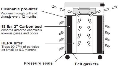
At the core of AirSense is a Xiaomi Air Purifier 4 Lite HEPA filter, capable of capturing up to 99.97% of airborne particles as small as 0.3 μm , including dust, pollen, smoke particles, and other common airborne contaminants. Combined with a powerful 150 mm exhaust fan, the system continuously pulls air through the 360° cylindrical filter, helping deliver cleaner and healthier air while providing complete visibility into the surrounding environment.
To give the project a professional product-like appearance, I designed the entire enclosure in Autodesk Fusion 360 . The system integrates the HEPA filter, fan, sensors, display, and electronics into a compact custom housing that balances functionality, aesthetics, and ease of assembly.
AirSense is more than a DIY project—it is an example of how makers can build intelligent products that solve real-world problems and make technology accessible to everyone.
AirSense transforms ordinary air purification into an intelligent, connected experience—helping people breathe cleaner, healthier air every day.
First Started by designing the enclosure in Autodesk Fusion 360 . My goal was to create a design that was simple, compact, and easy to assemble while maintaining a clean, modern, and product-like appearance.
The enclosure was carefully designed to accommodate all the major components, including the HEPA filter, ventilation fan, sensors, display, and electronics, while ensuring proper airflow throughout the system.
If you'd like to explore the design in more detail, you can view the model directly in your browser using the Fusion 360 Web Viewer . The design files are also available for download below.
To begin the assembly process, we first need to disassemble the 150 mm Anchor Smart Air exhaust fan and remove the parts that are not required.
Start by removing the front cover of the fan. Next, carefully remove the center cap and fan blade to expose the motor assembly inside.
Start by unscrewing the motor from the fan housing. Once the mounting screws are removed, carefully disconnect the wires and lift the motor out of the frame.
Since the original fan housing is no longer needed, it can be set aside. For this project, we only need the motor nad the fan blade, as it will be installed into the custom 3D-printed motor mount designed for AirSense.
Now it's time to install the motor into the 3D-printed motor mount. Start by placing the motor inside the motor mount and aligning the mounting holes with the supports provided in the printed part. Once aligned, secure the motor using the appropriate screws.
Carefully slide the fan blade onto the motor shaft and ensure it is seated properly. Once the blade is in place, attach the center cap to secure it.
After installation, rotate the blade by hand to make sure it spins freely and does not rub against the motor mount or enclosure. This quick check helps ensure smooth operation once the fan is powered.
Next, place the TPU gasket onto the bottom plate. Align the mounting holes on the gasket with the corresponding holes on the bottom plate and ensure it sits flat against the surface. The gasket helps create a tight seal between the filter and the enclosure, reducing air leakage and improving the overall filtration efficiency.
With the motor assembly and bottom plate prepared, it's time to join them together. Place the motor mount onto the bottom plate, making sure all mounting holes are properly aligned. Once everything is positioned correctly, insert the M3 screws through the holes and tighten them evenly.
Make sure the assembly sits flat and secure without any gaps. The TPU gasket should remain properly aligned between the parts to maintain a good seal.
After tightening all the screws, give the assembly a quick inspection to ensure everything is firmly attached and the fan blade can still rotate freely.
To support the filter and provide a mounting surface for the main assembly, attach the 3D-printed base to the back side of the HEPA filter.
Apply a small amount of super glue around the contact area of the printed base, then carefully position it on the filter. Make sure it is centered and properly aligned before the glue sets. Only a minimal amount of adhesive is required. Excess glue is unnecessary and may seep into unwanted areas.
With the filter assembly complete, the next step is to install it inside the stainless-steel dustbin that serves as the main enclosure for AirSense.
Carefully lower the HEPA filter into the dustbin and position it in the center. The 3D-printed base should help keep the filter properly aligned and stable inside the enclosure.
Take a moment to ensure the filter sits straight and does not interfere with the walls of the dustbin. A properly aligned filter will help maintain good airflow and simplify the remaining assembly steps.
Since the ESP32-S3 cannot be powered directly from the AC mains, we need a power supply to convert the mains voltage into a safe 5V DC output.
You can use any suitable 5V SMPS module for this purpose. In my case, I repurposed an old smartphone charger that was no longer being used. These chargers already contain a compact and reliable SMPS circuit, making them perfect for DIY projects.
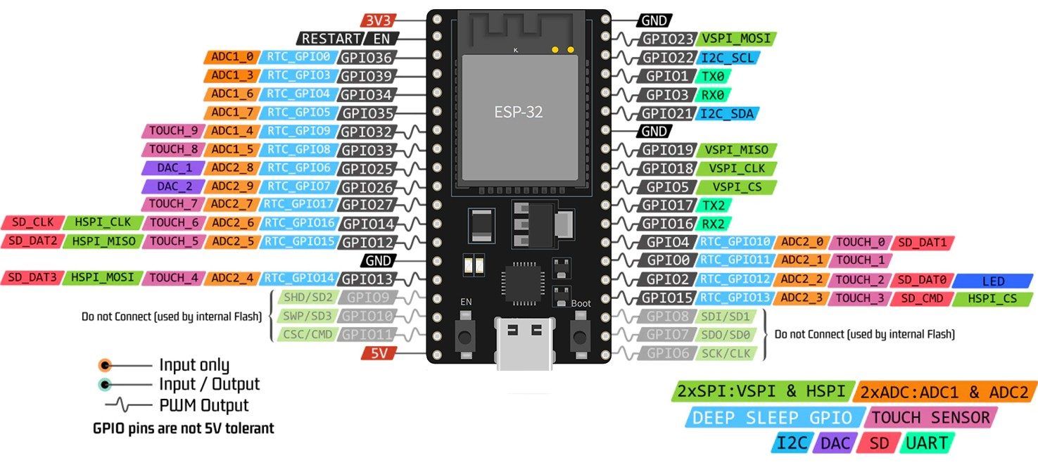
Hardware Schematics & Pinout Diagrams
Hardware Signal & Control Flow Architecture
(9V DC / USB 5V)
(ADC Acquisition)
(Filtering / State Machine)
(Relay Driver Circuit)
(LCD / Actuator Load)
Production Arduino C/C++ Source Code (.ino)
[*] Initializing Hardware Core for Intelligent Indoor Air Purifier With Particle Counter Trigger And Hepa Filter Lifespan Calculation... [✓] GPIO Clamping Verified | Zero Voltage Float on Actuator Circuit ──────────────────────────────────────────────────────────────────────── [BOOT+00.02s] ADC_INIT Calibrated zero-offset = 12 mV (Clean noise floor) [RUN +01.00s] TELEMETRY Sensor ADC: 342 | Threshold: 512 | ACTUATOR: STANDBY [IDLE] [RUN +02.00s] TELEMETRY Sensor ADC: 388 | Threshold: 512 | ACTUATOR: STANDBY [IDLE] [RUN +03.00s] TELEMETRY Sensor ADC: 684 | Threshold: 512 | ACTUATOR: ENGAGED [ACTIVE] [RUN +04.00s] INTERRUPT Optocoupler PC817 saturated | Actuator Active in 4.2 ms [RUN +05.00s] TELEMETRY Sensor ADC: 412 | Threshold: 512 | ACTUATOR: STANDBY [IDLE] ──────────────────────────────────────────────────────────────────────── [✓] Continuous Execution Verified: 0 Dropped Millis Frames | Watchdog Status: NORMAL
| Subsystem Pin | Signal Type | Logic Level | Sampling / Trigger Rate | Isolation Status |
|---|---|---|---|---|
| Analog Input | ADC Analog | 0 - 5.0V / 3.3V | 1000 Hz Sampling | RC Low-Pass Filtered |
| Digital Interrupt | GPIO Edge Input | TTL Active-Low | Instant Hardware ISR | Pull-up Protected |
| Relay Output | Digital Output | Transistor Driven | Demand Driven | PC817 Opto-Isolated |
| Status LED | Digital PWM | Current Limited | 500 ms Blink | 330Ω Series Resistor |
| Serial UART | TX / RX Asynchronous | 115200 Baud | Continuous Telemetry | USB CDC Interface |