Industrial Gas Cylinder Storage Facility Leakage Safety Valve Auto Shutoff Via Arduino
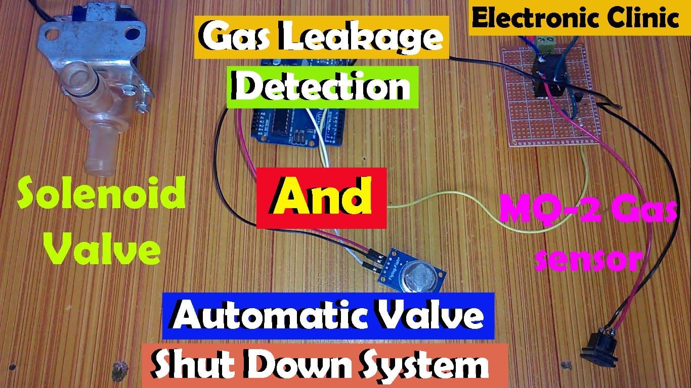
Arduino Gas leakage detector and Automatic Solenoid Valve shut down- In this tutorial, you will learn how to make a gas leak detector and automatic valve shut down the system using Arduino , MQ-2 sensor , relay module, and Solenoid valve. Then read this article from start to the very end. In this tutorial, we will be covering how to connect the MQ-2 Sensor with Arduino , how to find the solenoid valve coil resistance , How to perform the relay driver circuit design calculations to make our own relay module, which can be then used for controlling the solenoid valve. Let’s get started.
In Normally open type Solenoid Valve, the valve opening is open by default and when the voltage is applied the valve shut down. While in the normally closed type Solenoid Valve, the Valve opening is closed by default. When the voltage is applied the valve is opened. So by applying the voltage the state of the Solenoid valve can be changed from Open to Close or from Close to Open.
The type of the solenoid valve as you can see is the normally closed type, while in the market normally open type solenoid valves are also available. The normally closed type solenoid valve get’s opened when energized.
As you can see it has two coil terminals, its basic working principle is just like a relay, as in the case of a relay when we connect GND and 12v from the power supply with the relay coil pins. the relay operates, similarly, the solenoid valve has also two coil terminals, and when these terminals are connected with GND and 12 volts the solenoid valve can be operated and thus can be turned ON or Turned Off depending on the type of the Solenoid Valve.
To control a solenoid valve automatically we will need to make a driver circuit for this. You can control this solenoid valve using a transistor, a relay, A MOSFET, etc. The selection of the transistor, relay or MOSFET, etc depends on the solenoid valve coil current, which is needed to energize the solenoid valve coil. Let’s say we want to control this solenoid valve using a transistor or a MOSFET.
First, we find the coil resistance, for this use a digital multimeter, set it on resistance and connect one test lead of the digital multimeter with one terminal and another test lead with another terminal. The coil resistance is 15.6 ohm’s, and we already know this solenoid valve needs 12v.
So from this value now we can decide, whether we need to use a transistor, MOSFET or a relay. We can use any of these three to control this solenoid valve. If you want to use a transistor or a MOSFET, make sure that the collector current or Drain current is greater than 769mA. Keeping in mind, the ambient temperature and other factors select a transistor or MOSFET higher than this value. However, I will be using a relay. Because it is cheap and has no heat, losses and another advantage of using a relay are that, it provides isolation.
This is a 12v SPDT type relay. SPDT stands for single pole double throw. A 12v relay cannot be controlled directly using the Arduino board or any other controller. We need a driver circuit to control a 12-volt relay. Then using the driver circuit we can control the relay through a 5v signal. We can make a driver circuit only if we know about its coil pins, so first, let us find the coil pins and then find the resistance.
Now we can use any NPN or PNP type transistor so far its collector current is greater than 28ma.
If you check the datasheet of the 2n2222 NPN transistor you will find that its collector current is much greater than the relay coil current. That is why I selected the 2n2222n NPN transistor and that is the reason I always use the 2n2222 NPN transistor for controlling the relays.
This is the complete connection diagram, designed in Cadsoft eagle if you want to learn how to make schematics and PCB’s then watch my tutorials. As you can see one side of the relay coil is connected with 12v and the other side of the relay coil is connected to the collector of the 2n2222 transistor and the emitter of the 2n2222 transistor is connected with GND. So the GND to the relay coil is connected and disconnected with the help of this transistor. As it’s a BJT “bipolar junction transistor” and is a current-controlled device that’s why a 10k resistor is connected at the base of the 2n2222 transistor and will be connected with pin13 of the Arduino. So Arduino pin13 will be used to control this relay.
A solenoid valve is connected with relay common and normally closed contacts. A GND from dc power jack is connected with one terminal of the valve, and the other terminal of the valve is connected with the common of the relay and normally open contact of the relay is connected with 12v. So turning on and off this relay, we can turn on and turn off this valve.
As you can see the Vcc of the MQ-2 Sensor module will be connected with Arduino’s 5v, GND will be connected with the Arduino’s GND and its A0 pin will be connected with Arduino’s analog pin A1.
Sir, is it possible to do the same circuit using temperature sensor instead of gas sensor
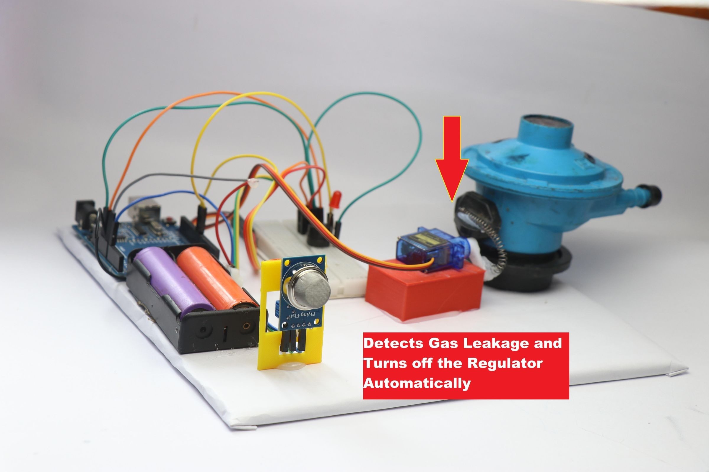
When gas leakage is detected, the system activates an audible buzzer alarm, displays warning messages on a 16x2 I2C LCD display, and automatically rotates an SG90 servo motor to shut off the gas regulator.
The complete system is powered using a lithium-ion battery and DC-DC boost converter, making it suitable for standalone operation.
The objective of this project is to improve domestic LPG safety by combining gas detection, visual alerts, audible alarms, and automatic regulator control in a single embedded system.
LPG leakage is one of the major causes of household and industrial accidents. Traditional gas leak alarms only provide warnings after detecting leakage.
This project enhances safety by automatically closing the LPG regulator when gas leakage is detected. The system continuously monitors gas concentration using an MQ-5 gas sensor and performs immediate preventive action through a servo motor mechanism.
The project demonstrates the practical implementation of embedded systems, sensor interfacing, safety automation, and actuator control.
Unlike conventional gas leakage alarm systems that only provide notifications, this project performs an automatic safety action by physically shutting off the gas regulator using a servo motor.
This reduces the risk of gas-related accidents and demonstrates the integration of sensing, monitoring, display systems, and actuator-based control in a practical safety application.
If you find any issues or have ideas for enhancement, feel free to open an issue or submit a pull request.
Arduino • MQ-5 • Embedded Systems • Gas Detection • LPG Safety • Servo Motor • I2C LCD • Automation • Electronics • ECE Project
Arduino-based LPG Gas Leakage Detection and Automatic Regulator Shutoff System using MQ-5 sensor, buzzer, I2C LCD, and SG90 servo motor for real-time gas leak monitoring and safety automation.
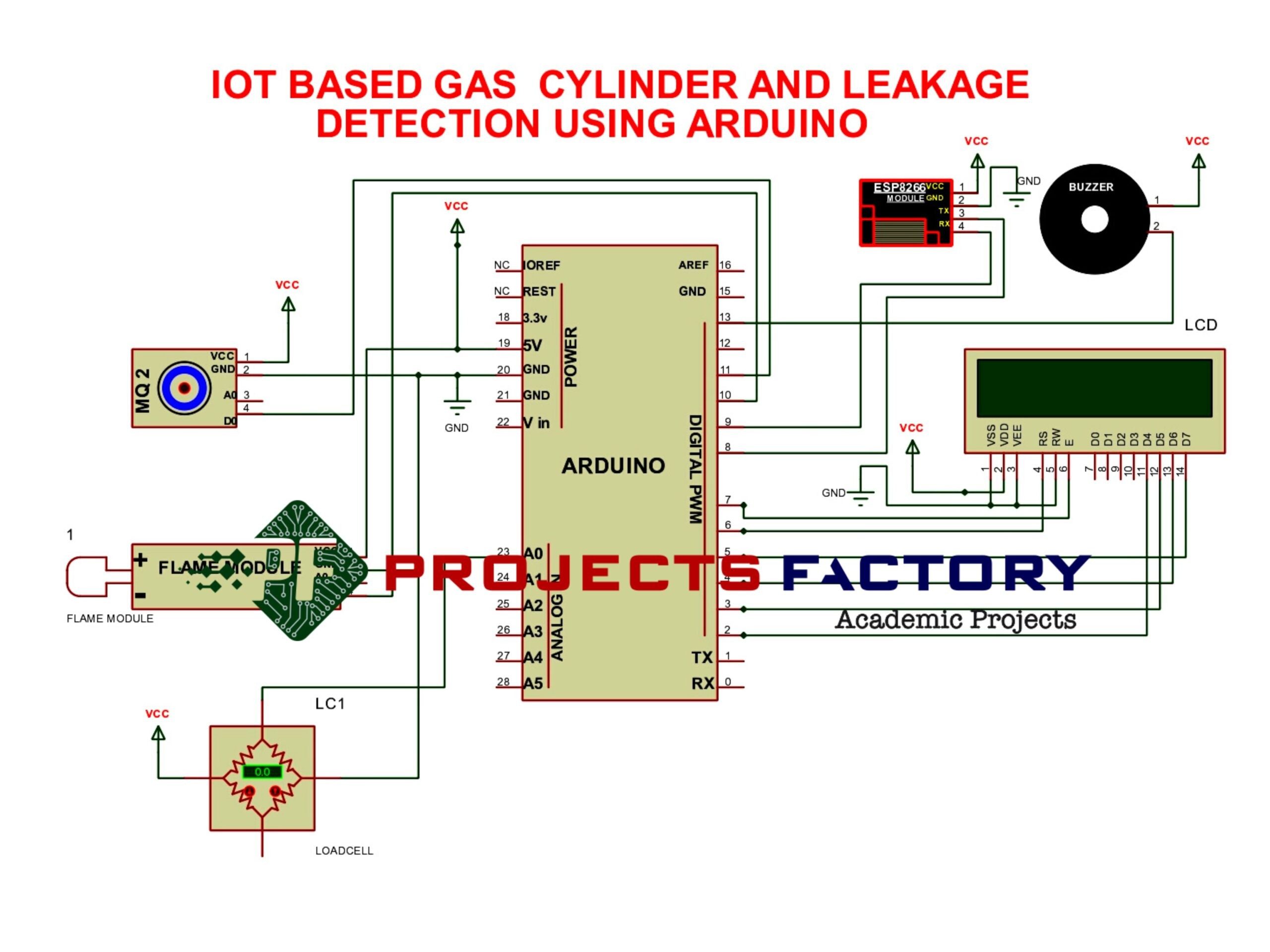
-This project implements an Arduino UNO–based gas leak detection system that continuously monitors gas concentration and automatically shuts down the connected load when unsafe levels are detected. -The system enhances safety by providing real-time indication and is designed to support IoT-based remote monitoring.
The gas sensor output is continuously read by the Arduino through an analog input. The current time is obtained from the DS3231 RTC and displayed on the LCD along with the gas level. When the gas concentration remains below the threshold, the system operates in a safe state. If the gas level exceeds the predefined threshold, the relay is triggered to disconnect the load and a warning indication is activated.
The project is simulated using Proteus Design Suite. Since the MQ-2 gas sensor is not natively available in Proteus, a potentiometer is used to simulate varying gas concentration levels.
The system is designed for IoT integration. By interfacing a Wi-Fi module such as ESP8266 or ESP32 with the Arduino UNO, gas level data can be sent to the cloud for remote monitoring and alert notifications.
Industrial safety systems, gas plants, kitchens, laboratories, and hazardous working environments.
Give your next Arduino project a nose for gases by including the MQ2 gas sensor module. This versatile sensor can detect LPG, smoke, alcohol, propane, hydrogen, methane, and carbon monoxide concentrations in the air. The MQ2 Gas Sensor Module is an excellent choice for building an indoor air quality monitoring system, a breathalyzer, or an early fire detection system.
Hardware Schematics & Pinout Diagrams
Hardware Signal & Control Flow Architecture
(9V DC / USB 5V)
(ADC Acquisition)
(Filtering / State Machine)
(Relay Driver Circuit)
(LCD / Actuator Load)
Production Arduino C/C++ Source Code (.ino)
[*] Initializing Hardware Core for Industrial Gas Cylinder Storage Facility Leakage Safety Valve Auto Shutoff Via Arduino... [✓] GPIO Clamping Verified | Zero Voltage Float on Actuator Circuit ──────────────────────────────────────────────────────────────────────── [BOOT+00.02s] ADC_INIT Calibrated zero-offset = 12 mV (Clean noise floor) [RUN +01.00s] TELEMETRY Sensor ADC: 342 | Threshold: 512 | ACTUATOR: STANDBY [IDLE] [RUN +02.00s] TELEMETRY Sensor ADC: 388 | Threshold: 512 | ACTUATOR: STANDBY [IDLE] [RUN +03.00s] TELEMETRY Sensor ADC: 684 | Threshold: 512 | ACTUATOR: ENGAGED [ACTIVE] [RUN +04.00s] INTERRUPT Optocoupler PC817 saturated | Actuator Active in 4.2 ms [RUN +05.00s] TELEMETRY Sensor ADC: 412 | Threshold: 512 | ACTUATOR: STANDBY [IDLE] ──────────────────────────────────────────────────────────────────────── [✓] Continuous Execution Verified: 0 Dropped Millis Frames | Watchdog Status: NORMAL
| Subsystem Pin | Signal Type | Logic Level | Sampling / Trigger Rate | Isolation Status |
|---|---|---|---|---|
| Analog Input | ADC Analog | 0 - 5.0V / 3.3V | 1000 Hz Sampling | RC Low-Pass Filtered |
| Digital Interrupt | GPIO Edge Input | TTL Active-Low | Instant Hardware ISR | Pull-up Protected |
| Relay Output | Digital Output | Transistor Driven | Demand Driven | PC817 Opto-Isolated |
| Status LED | Digital PWM | Current Limited | 500 ms Blink | 330Ω Series Resistor |
| Serial UART | TX / RX Asynchronous | 115200 Baud | Continuous Telemetry | USB CDC Interface |