Industrial Conveyor Roller Bearing Seizure Detection Using Non Contact Infrared Thermopiles
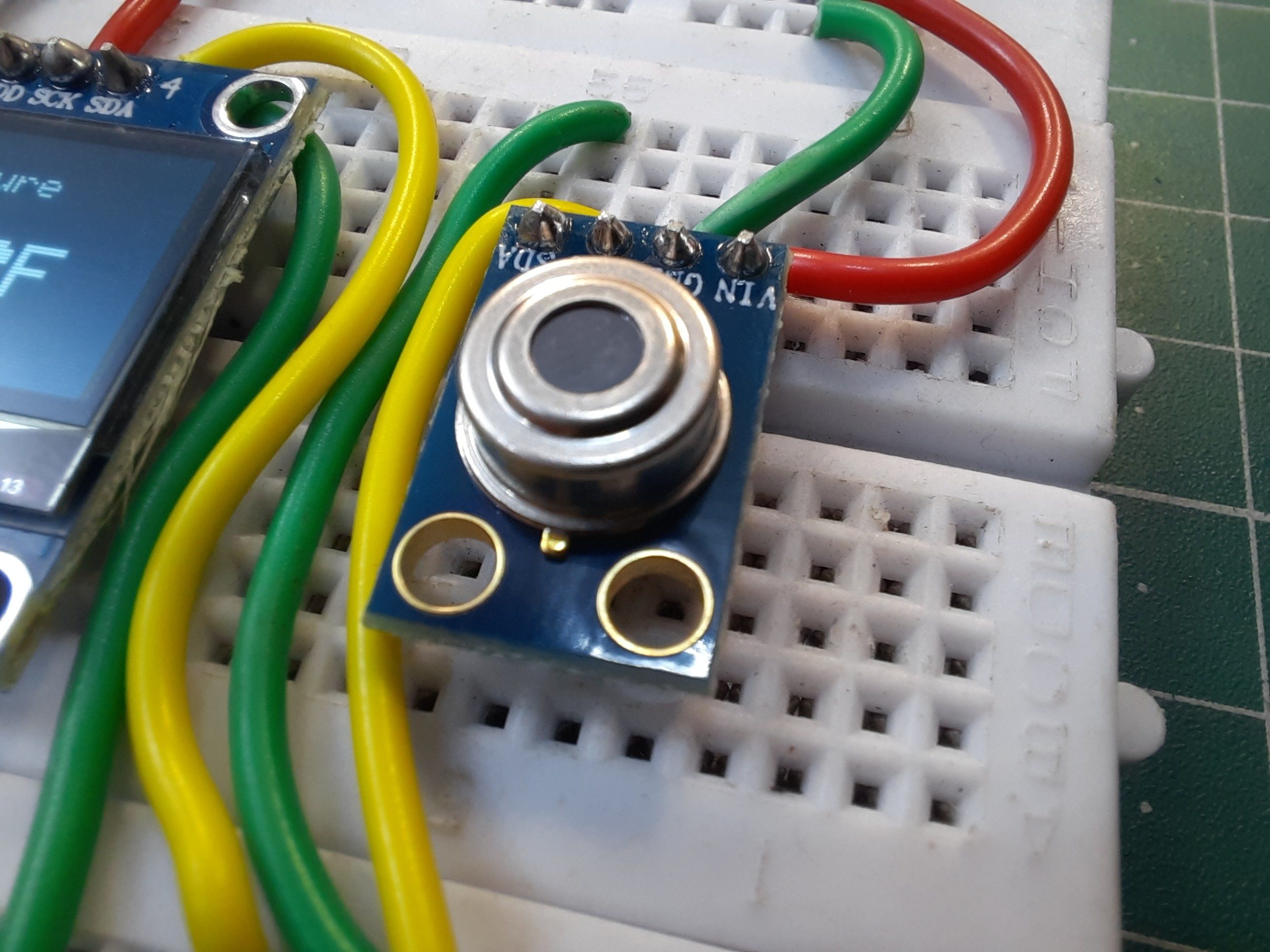
Since the emergence of COVID-19, non-contact infrared temperature scanners have been popping up everywhere around the world, from airports to restaurants. Maybe you are curious about these temperature scanners, or maybe you’re interested in building one. Well, in that case, the Melexis MLX90614 Module might be the best inexpensive option out there.
At the heart of the module is a high precision non-contact infrared temperature sensor from melexis – MLX90614 . Unlike most temperature sensors, this sensor measures temperature without being physically touched. This can be very useful for monitoring the temperature of something moving like a spinning motor shaft or objects on a conveyor belt for example. Simply point the sensor at what you want to measure and it will detect the temperature by absorbing the emitted IR waves.
The MLX90614 generates two temperature measurements: an object temperature and an ambient temperature. The object temperature is the non-contact measurement ‘observed’ from the sensor, while the ambient temperature measures the temperature on the die of the sensor. Ambient temperature can be used to calibrate the data, but what we really need comes from object temperature measurements.
Because it does not have to touch the object being measured, it can sense a wider range of temperatures than most digital sensors: object temperature measurements range from -70 to 382.2°C, while ambient temperature measurements range from -40 to 125°C. Both the ambient temperature and the object temperature have a resolution of 0.02°C with a standard accuracy of 0.5°C around room temperatures.
The MLX90614 has a built-in optical filter that cuts off visible and near-infrared light, reducing their effect on measurements. It also provides immunity against ambient light and sunlight.
The module comes with a 662K 3.3V precision voltage regulator and voltage level translator, so you can use it with your favorite 3.3V or 5V microcontroller without any worries.
The MLX90614 consumes less than 2mA during measurement. This low power consumption allows implementation in battery powered devices such as handheld thermal scanners.
If you’ve ever used or seen someone use an infrared thermometer before, you may have found yourself wondering, “How is this style of measurement even possible?”
Well, Infrared thermometers like MLX90614 take advantage of the fact that any object, including humans, above absolute zero (0°K or -273°C) temperature, emits (not visible to the human eye) light in the infrared spectrum that is directly proportional to its temperature. Refer to the Stefan–Boltzmann law .
Internally, the MLX90614 is a pair of two devices: an infrared thermopile detector and an ASSP (Signal-Conditioning Application Processor). Here is the internal block diagram of the MLX90614 showing both the thermopile and the ASSP.
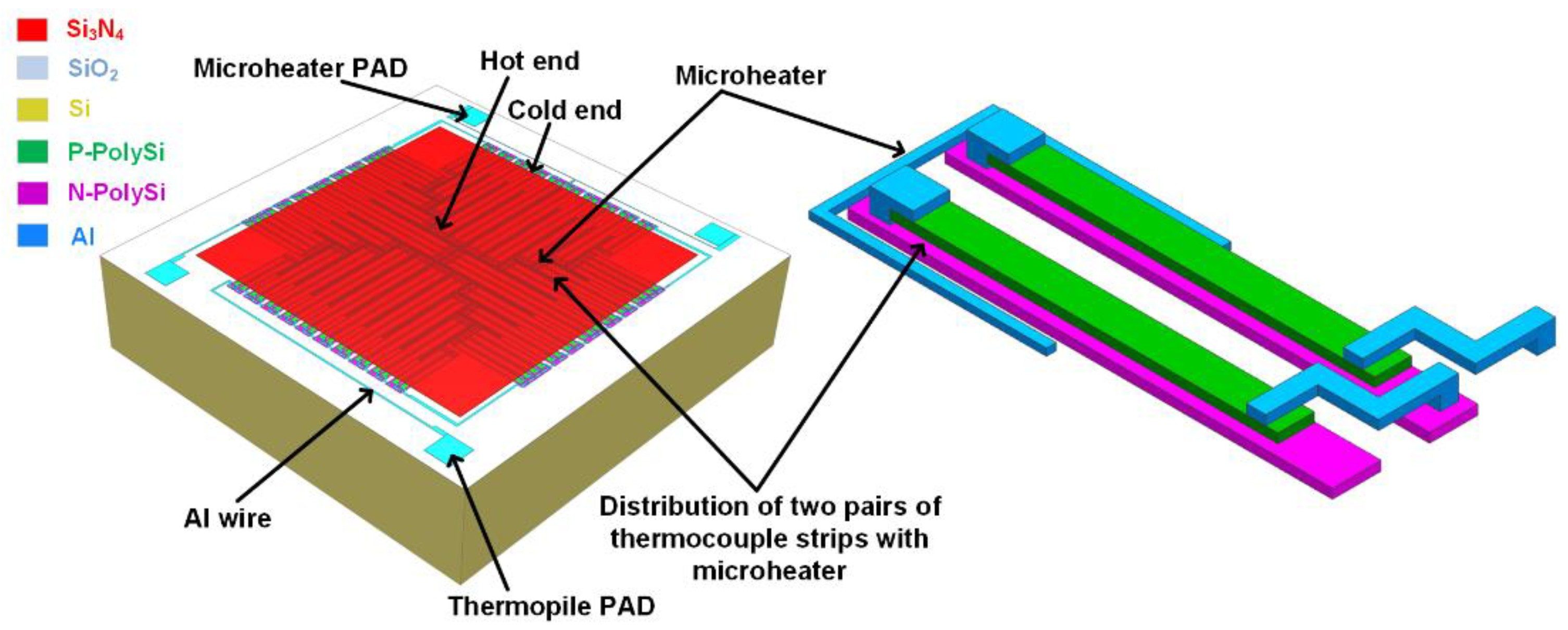
The IR radiation emitted by an object or human is first focused by a converging (convex) lens onto a special infrared detector called a Thermopile . The thermopile senses how much infrared energy is being emitted by objects in its field-of-view (FOV), and generates an electrical signal proportional to that.
The voltage produced by the thermopile is picked up by the ASSP’s 17-bit ADC and then processed before passing to the microcontroller.
And the best part is that this whole process is achieved in a fraction of a second.
An IR thermometer’s field-of-view (FOV) is one of the most important metrics to be aware of.
It is determined by the angle in which the sensor is sensitive to thermal radiation. This means that the sensor will detect all objects in the field-of-view and return the average temperature of all objects in it.
It is important that the measured object completely fills the field-of-view. Otherwise, the sensor may detect objects that are not supposed to be measured, resulting in inaccurate measurements.
The field-of-view also determines the relationship between the distance from an object and the sensing area. If the sensor is near the object, its sensing area is very narrow, but gets increasingly wider as it moves farther away.
The field-of-view of the MLX90614 is cone-shaped and relatively wide: 90°. This means that for every 1cm you move away from an object, the sensing area increases by 2cm. If you are one foot 30cm (approx. 1 foot) away from an object, the sensing area will be 60cm (approx. 2 feet).
The MLX90614 supports two interfaces; though you will need one to access the other. The 2-wire SMBus interface is the primary means of communicating with the MLX90614. Once the SMBus interface is set up, you can later configure the MLX90614 to produce a PWM (pulse-width-modulated) signal representing the measured temperature.
The primary interface to the MLX90614 is the 2-wire SMBus interface which is basically the same as I2C (a slightly non-standard type of I2C called “repeated-start”) and uses the same two signals – SDA and SCL – to carry data and clock signals respectively. A master device controls the clock signal, while the data signal is controlled bi-directionally.
Every MLX90614 has a default I2C address of 0x5A. However, it can be programmed to have one of 127 I2C addresses so that you can add up to 127 devices to the same bus to get a larger temperature map.
The MLX90614’s data can also be read through the PWM interface. Note that in order to use the PWM interface, the MLX90614 must first be configured over the SMBus.
Once configured, the MLX90614 outputs a continuous 10-bit PWM signal on the SDA pin that represents the measured object temperature. By default the PWM signal covers the range of -20°C to 120°C with an output resolution of 0.14°C, but this can also be adjusted via SMBus.
By configuring this range (setting minimum and maximum temperature values) the PWM output can be turned into a “Thermal Relay/Thermal Switch” signal.
So when the temperature exceeds the set threshold, the PWM pin is triggered which can be used as an interrupt source or can be used to directly control a relay. Note that the output drive capability is 25mA only.
Now that we know everything about the module, we can begin hooking it up to our Arduino!
Start by connecting the VCC pin to the power supply, 5V is fine. Use the same voltage that your microcontroller logic is based off of. For most Arduinos, that is 5V. For 3.3V logic devices, use 3.3V. Now connect GND to common ground.
Connect the SCL pin to the I2C clock pin and the SDA pin to the I2C data pin on your Arduino. Note that each Arduino Board has different I2C pins which should be connected accordingly. On the Arduino boards with the R3 layout, the SDA (data line) and SCL (clock line) are on the pin headers close to the AREF pin. They are also known as A5 (SCL) and A4 (SDA).
There are several libraries available for the MLX90614 sensor. However in our example, we are using the Adafruit library which is very easy to use, but it only supports basic temperature measurement and not the advance features of the sensor. The library can be downloaded from within the Arduino IDE Library Manager.
To install the library navigate to the Sketch > Include Library > Manage Libraries… Wait for Library Manager to download libraries index and update list of installed libraries.
Filter your search by typing ‘ adafruit mlx90614 ‘. Click on the entry, and then select Install.
Below is a basic Arduino sketch that allows you to quickly test the functionality of the MLX90614. Go ahead and upload it to your Arduino. You should see the ambient and object temperature printed on the serial interface.
Once the sketch is uploaded, open your serial monitor, setting the baud rate to 9600 bps. You should see both the ambient temperature and the object temperature begin to stream by.
Try pointing the sensor at objects lying around you or pointing it at your forehead to make sure you don’t have a fever!
Electromagnetic interference can give incorrect results. So while using an infrared thermometer, make sure that your phone, microwave, WiFi router, TV or any electrical device is completely away.
The sketch starts with including the Adafruit_MLX90614 library. In that same global area, an Adafruit_MLX90614 object called mlx is defined.
In the setup, we initialize the serial communication with PC and call the begin function.
The begin function initializes I2C interface. This function optionally takes a parameter (the 7-bit address of your sensor) but if left empty it assumes the address is set to the default (0x5A).
In the loop, we simply print the current ambient and object temperatures using the readAmbientTempC / mlx.readAmbientTempF and readObjectTempC / readObjectTempF functions.
In today’s rapidly evolving manufacturing landscape, industrial automation is no longer optional — it is essential. Modern production lines demand precision, reliability, quality assurance, and safety integration at every stage of operation. To meet these growing industry requirements, Arduino Expert successfully designed and developed a fully customized Automated Conveyor Control and Inspection System for one of our industrial clients.
This project demonstrates our expertise in Product Design and Development , Industrial Project Development , Custom Electronics Project Development , and Embedded Systems Development for real-world manufacturing applications.
Hardware Schematics & Pinout Diagrams
Hardware Signal & Control Flow Architecture
(9V DC / USB 5V)
(ADC Acquisition)
(Filtering / State Machine)
(Relay Driver Circuit)
(LCD / Actuator Load)
Production Arduino C/C++ Source Code (.ino)
[*] Initializing Hardware Core for Industrial Conveyor Roller Bearing Seizure Detection Using Non Contact Infrared Thermopiles... [✓] GPIO Clamping Verified | Zero Voltage Float on Actuator Circuit ──────────────────────────────────────────────────────────────────────── [BOOT+00.02s] ADC_INIT Calibrated zero-offset = 12 mV (Clean noise floor) [RUN +01.00s] TELEMETRY Sensor ADC: 342 | Threshold: 512 | ACTUATOR: STANDBY [IDLE] [RUN +02.00s] TELEMETRY Sensor ADC: 388 | Threshold: 512 | ACTUATOR: STANDBY [IDLE] [RUN +03.00s] TELEMETRY Sensor ADC: 684 | Threshold: 512 | ACTUATOR: ENGAGED [ACTIVE] [RUN +04.00s] INTERRUPT Optocoupler PC817 saturated | Actuator Active in 4.2 ms [RUN +05.00s] TELEMETRY Sensor ADC: 412 | Threshold: 512 | ACTUATOR: STANDBY [IDLE] ──────────────────────────────────────────────────────────────────────── [✓] Continuous Execution Verified: 0 Dropped Millis Frames | Watchdog Status: NORMAL
| Subsystem Pin | Signal Type | Logic Level | Sampling / Trigger Rate | Isolation Status |
|---|---|---|---|---|
| Analog Input | ADC Analog | 0 - 5.0V / 3.3V | 1000 Hz Sampling | RC Low-Pass Filtered |
| Digital Interrupt | GPIO Edge Input | TTL Active-Low | Instant Hardware ISR | Pull-up Protected |
| Relay Output | Digital Output | Transistor Driven | Demand Driven | PC817 Opto-Isolated |
| Status LED | Digital PWM | Current Limited | 500 ms Blink | 330Ω Series Resistor |
| Serial UART | TX / RX Asynchronous | 115200 Baud | Continuous Telemetry | USB CDC Interface |