Industrial Boiler Steam Drum Pressure And Water Level Safety Interlock System Via Arduino
Modernize legacy thermal assets with intelligent, open-architecture control. As an Arduino Pro Design Partner , we transform Arduino Opta and Portenta hardware into ruggedized Boiler Control Systems that optimize fuel-to-air ratios, reduce emissions, and provide 24/7 remote oversight. Do you need to build something like this?
Utilize the Arduino Opta (PLC) to manage the critical safety interlocks, purge cycles, and flame supervision logic required for industrial-grade steam and hot water boilers.
Leverage the Portenta Machine Control to run complex PID loops that adjust oxygen trim and fuel flow in real-time, reducing fuel consumption by up to 10–15% compared to legacy mechanical linkage systems.
Automatically log steam pressure, stack temperature, and fuel usage to the Arduino Cloud or a local SCADA system, ensuring 100% compliance with environmental reporting and boiler safety inspections.
Legacy boiler controllers are often proprietary “black boxes” that limit optimization and drive up maintenance costs.
With our Arduino industrial expertise, we can build a professional boiler automation system. Granting your engineering team absolute transparency and control over your facility’s primary energy source.
In steam-intensive production, we synchronize boiler output with real-time demand. By eliminating "short-cycling," we drastically extend the operational lifecycle of boiler tubes and reduce peak-load fuel consumption.
For high-temperature reactors, our system monitors flue-gas and combustion parameters to detect soot or scale buildup early. This enables a predictive maintenance model that prevents thermal efficiency decay and unplanned downtime.
To ensure uncompromised safety, we engineer custom interfaces with galvanic isolation for all 0-10V and 4-20mA sensor loops. High-reliability industrial relays manage fuel valves and ignition transformers, ensuring the logic thrives in the extreme heat and vibration of the boiler room.
We bridge the gap between “standard PLC logic” and the high-level data needs of modern boiler control systems:
Unlike traditional burner-management systems, our Arduino Pro solutions are built on open-source standards. Your in-house team owns the code and can adjust setpoints or logic without a $5,000 service call from a specialized technician.
Industrial boilers require absolute fail-safes. We engineer custom carrier boards with dual-channel safety relays, hardware watchdog timers, and massive EMI shielding to protect the MCU from ignition transformer noise, ensuring your system fails safely under any circumstance.
General electronics certifications (like basic CE/FCC) aren’t enough for the boiler room. We design your hardware architectures with the rigorous physical and logical separation required to fast-track compliance with strict combustion safety standards like NFPA 85 and UL 353.
Customizing your boiler controls with Arduino Pro technology eliminates bloated overhead, directly accelerating your project’s return on investment.
By deploying precision boiler control systems, you achieve enterprise-grade reliability at a fraction of the cost of traditional, restrictive off-the-shelf systems.
Partnering with DeepSea Developments ensures these custom solutions are expertly orchestrated to deliver peak performance and long-term operational value.
"We deliver transparent, open-architecture hardware and software that you fully own, engineered to your exact, long-term operational standard."
Fill out the form to know how we can build Arduino Pro-based devices for your industry
Hardware Schematics & Pinout Diagrams
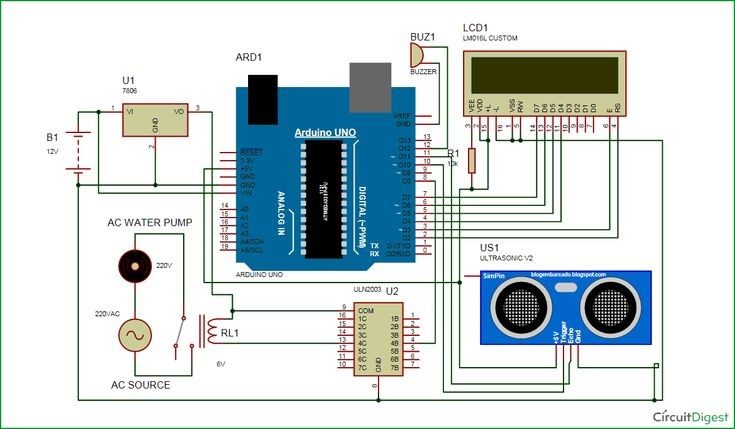
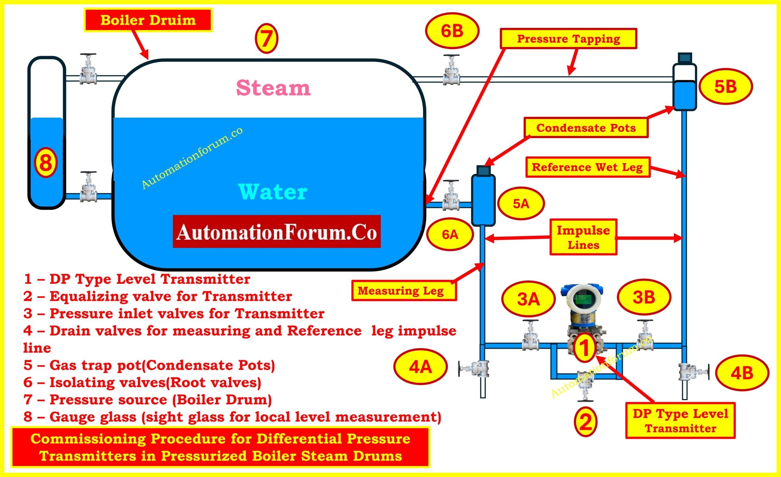
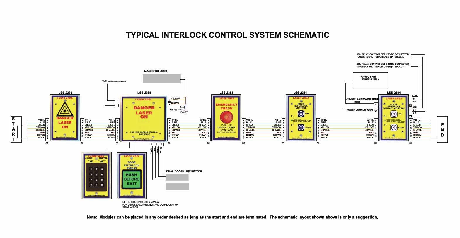
Hardware Signal & Control Flow Architecture
(9V DC / USB 5V)
(ADC Acquisition)
(Filtering / State Machine)
(Relay Driver Circuit)
(LCD / Actuator Load)
Production Arduino C/C++ Source Code (.ino)
[*] Initializing Hardware Core for Industrial Boiler Steam Drum Pressure And Water Level Safety Interlock System Via Arduino... [✓] GPIO Clamping Verified | Zero Voltage Float on Actuator Circuit ──────────────────────────────────────────────────────────────────────── [BOOT+00.02s] ADC_INIT Calibrated zero-offset = 12 mV (Clean noise floor) [RUN +01.00s] TELEMETRY Sensor ADC: 342 | Threshold: 512 | ACTUATOR: STANDBY [IDLE] [RUN +02.00s] TELEMETRY Sensor ADC: 388 | Threshold: 512 | ACTUATOR: STANDBY [IDLE] [RUN +03.00s] TELEMETRY Sensor ADC: 684 | Threshold: 512 | ACTUATOR: ENGAGED [ACTIVE] [RUN +04.00s] INTERRUPT Optocoupler PC817 saturated | Actuator Active in 4.2 ms [RUN +05.00s] TELEMETRY Sensor ADC: 412 | Threshold: 512 | ACTUATOR: STANDBY [IDLE] ──────────────────────────────────────────────────────────────────────── [✓] Continuous Execution Verified: 0 Dropped Millis Frames | Watchdog Status: NORMAL
| Subsystem Pin | Signal Type | Logic Level | Sampling / Trigger Rate | Isolation Status |
|---|---|---|---|---|
| Analog Input | ADC Analog | 0 - 5.0V / 3.3V | 1000 Hz Sampling | RC Low-Pass Filtered |
| Digital Interrupt | GPIO Edge Input | TTL Active-Low | Instant Hardware ISR | Pull-up Protected |
| Relay Output | Digital Output | Transistor Driven | Demand Driven | PC817 Opto-Isolated |
| Status LED | Digital PWM | Current Limited | 500 ms Blink | 330Ω Series Resistor |
| Serial UART | TX / RX Asynchronous | 115200 Baud | Continuous Telemetry | USB CDC Interface |