Home Aquarium Automated Feeder
IR receiver connect to gnd and 5v and the third pin to pin 2 in arduino nano board
Random freezes, missing sound and display glitches usually trace back to one bad driver. Find and replace yours safely.
You can build an Arduino fish feeder that releases dry food on a schedule using an Arduino Uno or Nano, a DS3231 real-time clock (RTC), and a servo-operated gate or metering mechanism. The electronics are straightforward; reliable portions are the harder part. Calibrate the mechanism with your fish’s actual food, then supervise it for at least a week before relying on it. A servo command does not prove that food reached the tank.
The RTC keeps time, the Arduino checks it against scheduled feedings, and a servo moves a gate, drum, or slide to release food. A one-shot flag prevents the same scheduled event from triggering repeatedly.
This is a practical DIY project if you want to customize the schedule, learn Arduino, or add sensors. It is not automatically cheaper or more dependable than a ready-made feeder, especially if you must buy every part. Commercial units may include battery operation, enclosed food chambers, mounting hardware, or Wi-Fi, depending on the model. For example, EHEIM’s standard autofeeder is designed for scheduled dry-food dispensing and includes a ventilated food chamber.
Build the DIY version for customization and learning; choose a commercial feeder when quick setup and an enclosed, purpose-built unit matter more. Either way, portion size depends on the food and mechanism, not merely the schedule.
For a first build, use a small servo to actuate a gate or a fixed-volume chamber. Do not assume that holding a flap open for a particular number of milliseconds corresponds to a fixed mass of food.
Useful additions include a manual-feed button, status LED, display, low-food sensor, mechanical stop, and splash-protected enclosure. Start with the simplest design you can test thoroughly. Arduino examples range from a basic servo feeder to systems with an RTC, display, buttons, and sensors, such as this Arduino aquarium project .
For an Uno or classic Nano, connect the DS3231 as follows. Other Arduino-compatible boards may use different I2C pins, so check the pinout for your exact board.
Connect the servo signal wire to digital pin 9 in the example below. Connect its power wire to a regulated supply appropriate for that servo, and connect the supply ground to Arduino GND. The common ground gives the signal a shared reference; it does not mean the servo should draw power through the Arduino. The Arduino Servo library is a standard starting point for hobby servo control.
Servo startup or stall current can cause jitter, resets, or missed feedings if the supply is inadequate. Use a stable supply rated for the load, keep wiring secure, reduce mechanical binding, and avoid forcing the servo against a hard stop. Keep the controller and power connections above the tank, away from condensation and splash paths; add strain relief and arrange cables so water cannot run along them into electrical equipment.
In the Arduino IDE, install RTClib through Library Manager if it is not already available. The sketch also uses the built-in Wire and Servo libraries. Avoid downloading an arbitrary library copy from an unverified source.
Set the RTC’s date and time during commissioning, then verify the result by printing or otherwise checking rtc.now . A common mistake is leaving time-adjustment code active in the final sketch: it resets the clock whenever the Arduino restarts. In the example below, the adjustment line is commented out. If you temporarily enable it to set the time from the computer’s compile time, upload once, verify the RTC, and comment it out again before the normal upload. Account for the time zone you want feeding schedules to use; compile time is not a substitute for confirming the module’s displayed time.
This teaching sketch checks the hour and minute rather than relying on a single exact second. It marks each schedule complete for the current date, so a loop that runs repeatedly during the matching minute does not dispense repeatedly.
Change the hour and minute arrays to the schedule you want, using 24-hour time. The servo angles and OPEN_TIME_MS are starting values for testing, not universal settings. The sketch’s completion flags live in RAM: if the Arduino loses power and restarts during a scheduled minute, it can forget that event was served. For a more robust unattended design, store the date and schedule index of the last completed event in nonvolatile memory, and define a deliberate recovery policy for resets. A short delay is acceptable for a simple prototype, but a state machine using millis is preferable if you add buttons, jam detection, a display, or network features. The schedule logic should never dispense repeatedly just because the clock remains in the matching minute.
The RTC backup cell preserves time; it does not power the Arduino or servo and cannot dispense food during an outage. If feeding during power loss is required, design and test a separate backup supply for the complete system.
Use dry food only: flakes, pellets, or granules that fit the outlet and mechanism. Wet, frozen, or refrigerated foods need a different storage and dispensing approach. Food size and shape matter; manufacturers also warn that oversized dry food can clog an outlet. See the food compatibility guidance on EHEIM’s product information .
A fixed-volume chamber is usually a better starting point for repeatability than simply leaving a flap open for a set time. Even a chamber still needs testing with the chosen food: pellets, granules, and flakes do not pack or flow alike.
If food lands outside the feeding area or fish do not eat it, reduce the portion, check water flow and outlet placement, and schedule feeding when the species are active. Observe normal cycles in the actual aquarium before leaving the feeder to operate alone.
A DIY Arduino feeder is a good fit when you want to customize a mechanism, add local sensors, or learn how the system works—and can take responsibility for testing and maintenance. Buy a purpose-built feeder if you need a quicker setup, enclosed food storage, or a mounting arrangement designed for an aquarium. A dual-chamber model can suit separate dry foods; a Wi-Fi feeder may offer remote control or alerts but adds network dependence and may require mains power. Arduino’s connected feeder example shows the Wi-Fi route, but network access should not be the sole safeguard against missed feedings.
No schedule guarantees the right nutrition or proves that food was dispensed. Use a kitchen scale when portion size matters, test any feeder with the actual food, and choose based on whether customization or ready-to-use operation is more important. Product features, regional availability, and pricing vary; check the manufacturer for the particular model and market.
Before you go - each of these free tools takes about a minute and tackles what quietly slows a Windows PC down.
Hardware Schematics & Pinout Diagrams
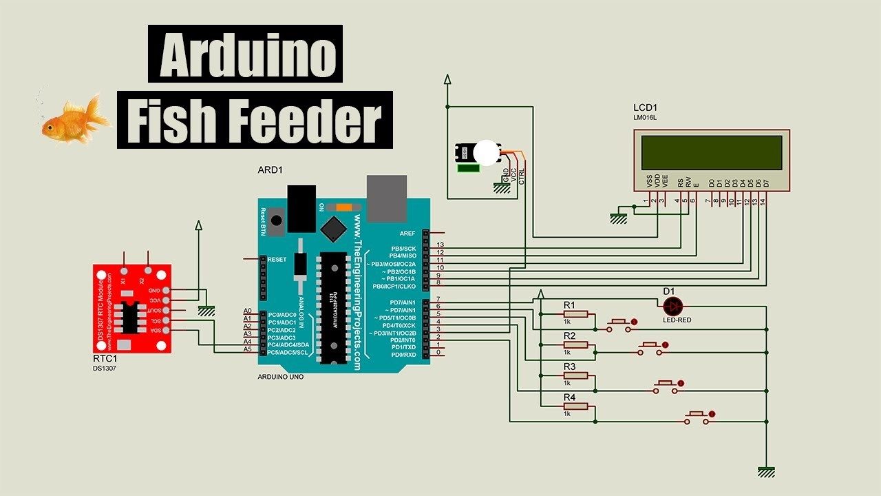
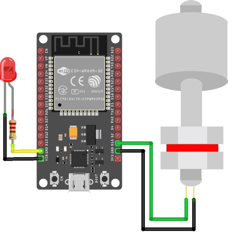
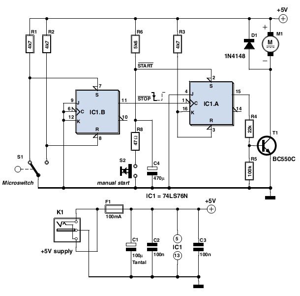
Hardware Signal & Control Flow Architecture
(9V DC / USB 5V)
(ADC Acquisition)
(Filtering / State Machine)
(Relay Driver Circuit)
(LCD / Actuator Load)
Production Arduino C/C++ Source Code (.ino)
[*] Initializing Hardware Core for Home Aquarium Automated Feeder... [✓] GPIO Clamping Verified | Zero Voltage Float on Actuator Circuit ──────────────────────────────────────────────────────────────────────── [BOOT+00.02s] ADC_INIT Calibrated zero-offset = 12 mV (Clean noise floor) [RUN +01.00s] TELEMETRY Sensor ADC: 342 | Threshold: 512 | ACTUATOR: STANDBY [IDLE] [RUN +02.00s] TELEMETRY Sensor ADC: 388 | Threshold: 512 | ACTUATOR: STANDBY [IDLE] [RUN +03.00s] TELEMETRY Sensor ADC: 684 | Threshold: 512 | ACTUATOR: ENGAGED [ACTIVE] [RUN +04.00s] INTERRUPT Optocoupler PC817 saturated | Actuator Active in 4.2 ms [RUN +05.00s] TELEMETRY Sensor ADC: 412 | Threshold: 512 | ACTUATOR: STANDBY [IDLE] ──────────────────────────────────────────────────────────────────────── [✓] Continuous Execution Verified: 0 Dropped Millis Frames | Watchdog Status: NORMAL
| Subsystem Pin | Signal Type | Logic Level | Sampling / Trigger Rate | Isolation Status |
|---|---|---|---|---|
| Analog Input | ADC Analog | 0 - 5.0V / 3.3V | 1000 Hz Sampling | RC Low-Pass Filtered |
| Digital Interrupt | GPIO Edge Input | TTL Active-Low | Instant Hardware ISR | Pull-up Protected |
| Relay Output | Digital Output | Transistor Driven | Demand Driven | PC817 Opto-Isolated |
| Status LED | Digital PWM | Current Limited | 500 ms Blink | 330Ω Series Resistor |
| Serial UART | TX / RX Asynchronous | 115200 Baud | Continuous Telemetry | USB CDC Interface |