High Speed Rotating Shaft Tachometer With Optical Slotted Disc And Microsecond Interpolation
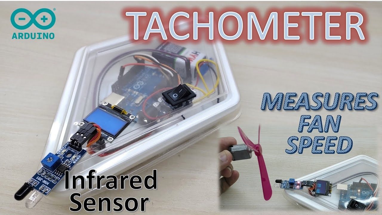
The IR slotted optical speed sensor is a small U-shaped module. People also call it a slot sensor, an opto interrupter or a U-shaped IR sensor. It tells Arduino if something is inside its slot or not. With an encoder disc, it can also tell how fast a motor or a wheel turns.
The pin order may be different between batches. Please read the labels on your module.
One side of the U has an infrared LED. The other side has an NPN phototransistor. They face each other across the 5.9 mm slot.
The built-in Schmitt trigger makes the output a clean and stable 0 or 1, with no jitter. So we do not need to debounce it in the code.
An encoder disc is a round plate with slots (holes) near its edge. The common disc for TT gear motors has 20 slots. Fix the disc on the motor shaft or on the wheel, so its teeth pass through the slot of the sensor without touching it.
When the disc spins, each tooth blocks the light for a moment. The OUT pin gives one pulse per tooth. One full turn gives 20 pulses. Arduino counts the pulses in 1 second and then works out the speed:
Connect VCC of the sensor to 5V of Arduino, GND to GND , and OUT to pin 2 of Arduino, as shown in the image below.
We use pin 2 because it is an interrupt pin on Arduino Uno. The RPM code needs it.
Why use an interrupt? When the motor spins fast, the pulses are very short. If we only check the pin in loop , we may miss some of them. The interrupt catches every pulse. We use FALLING so each tooth is counted only once.
The code uses SLOTS_PER_TURN = 20 . If your encoder disc has a different number of slots, change this number.
Do you want to find the distance a wheel travels? Multiply the number of turns by the wheel circumference (Ï Ã wheel diameter).
If you want to detect an object at a distance (not inside a slot), see Arduino - Infrared Obstacle Avoidance Sensor . If you want to read a knob and its direction, see Arduino - Rotary Encoder .
Master the Arduino RPM sensor interface. Learn to wire an LM393 optical module, use hardware interrupts, and write precise tachometer code.
Measuring the rotational speed of a motor, wheel, or shaft is a foundational skill in robotics and automation. When building a tachometer, the term arduino rpm sensor usually refers to one of two underlying technologies: optical interruption or magnetic Hall effect sensing. For beginners, the LM393 slotted optical sensor module is the undisputed starting point. It offers digital output, simple threshold adjustment, and requires no complex analog-to-digital conversion. However, successfully reading high-speed rotations requires moving beyond basic polling loops and embracing hardware interrupts.
In this comprehensive 2026 guide, we will interface the widely available LM393 optical speed sensor module with an Arduino Uno R4 Minima. We will cover the exact wiring, provide production-ready C++ code using microsecond timing, and explore the real-world edge cases that cause RPM readings to fluctuate or fail entirely.
Before wiring anything, it is crucial to understand the physical limitations of your sensor type. Optical sensors rely on an infrared (IR) beam breaking across a physical gap, while magnetic sensors detect changes in magnetic flux. Here is how the most common hobbyist modules compare in real-world applications:
To build a robust, high-resolution tachometer, you will need the following components. Prices reflect early 2026 market averages from major electronics distributors:
The LM393 module typically features four pins: VCC, GND, DO (Digital Output), and AO (Analog Output). For RPM counting, we exclusively use the Digital Output pin, which triggers LOW when the IR beam is broken and HIGH when it is clear. The onboard potentiometer adjusts the ambient light threshold, but we rely on the digital comparator for clean square waves.
Note: Leave the AO (Analog Output) pin disconnected. Reading analog values introduces a ~100μs delay per read, which is catastrophic for high-speed tachometry.
The most common mistake beginners make when coding an arduino rpm sensor is using millis or counting pulses over a fixed one-second window. Both methods introduce massive quantization errors at high speeds. Instead, we measure the exact time between individual pulses using micros and hardware interrupts.
According to the official Arduino attachInterrupt Documentation , executing an Interrupt Service Routine (ISR) pauses the main program, ensuring no pulses are missed even if the microcontroller is busy driving a display or PID loop.
Let us break down the math. If a motor is spinning at 6,000 RPM with a 20-slot disc, it generates 2,000 pulses per second. That means one pulse occurs every 0.5 milliseconds (500μs). The millis function only updates every ~1ms. If you use millis , your time delta will alternate between 0 and 1, resulting in RPM calculations that wildly swing between 0 and infinity. The micros function resolves down to 4μs on the Uno R4, providing a highly stable time delta for accurate velocity calculations.
Theoretical code often fails when exposed to physical realities. As detailed in the Texas Instruments LM393 Datasheet , the comparator's response time is roughly 1.3μs, which is plenty fast. The bottleneck is almost always optical physics and mechanical alignment.
The LM393 module uses unmodulated infrared LEDs. This makes it highly susceptible to ambient sunlight, which contains massive amounts of IR radiation. If your robot or motor is operating outdoors or near a south-facing window, the receiver phototransistor will become saturated, and the digital output will lock HIGH. The Fix: 3D print a small, opaque shroud (using black PLA or PETG) that slips over the sensor U-channel. This physical light baffle is mandatory for any outdoor or brightly lit environment deployment.
Even with perfect code, you may notice the RPM reading jittering by 5-10% at steady speeds. This is usually caused by mechanical 'wobble' or electrical switch bounce. Follow this diagnostic checklist:
Interfacing an arduino rpm sensor is a rite of passage for embedded systems engineers. By abandoning polling loops in favor of hardware interrupts, utilizing microsecond timing, and respecting the optical limitations of the LM393 module, you can build a tachometer that rivals commercial industrial equipment. Always remember that in sensor integration, the physical mounting and light isolation are just as critical as the C++ code running on the silicon.
Learn how to wire and code Arduino interrupt pins for high-speed signals. Includes an RPM tachometer build, pin maps, and ISR debugging steps.
The classic Arduino Uno R3 has exactly two dedicated hardware interrupt pins: Digital 2 (INT0) and Digital 3 (INT1) . If you are polling a sensor in your main loop using digitalRead , you are limited by the execution time of your other code. If your loop takes 5ms to run, you will entirely miss a 2ms pulse from a high-speed rotary encoder or a hall effect sensor. Hardware interrupts bypass the main loop, immediately pausing your code to execute an Interrupt Service Routine (ISR) the microsecond a pin changes state.
While modern boards like the ESP32 DevKit V1 support hardware interrupts on almost all GPIOs (except 6-11, and 34-39 which are input-only), the ATmega328P architecture on the Uno R3 remains the baseline for learning strict ISR discipline. According to the official Arduino attachInterrupt reference , relying on hardware interrupts is mandatory for signals exceeding 100Hz if your main loop handles blocking tasks like Serial.print or I2C display updates.
To demonstrate interrupt mechanics, we are building a non-contact RPM tachometer. This reads a magnet passing by a hall effect sensor, calculating revolutions per minute without bogging down the main processor.
It uses the FALLING edge trigger because the A3144 pulls the line LOW when a magnetic south pole is detected. Notice the strict use of the volatile keyword and the critical section ( noInterrupts / interrupts ) used to safely copy the ISR variable into the main loop.
When your interrupt-driven circuit behaves erratically, freezes, or fails to compile, follow this ranked diagnostic path.
The Cause: You are attempting to use a pin that does not support hardware interrupts on your specific board variant, or you are using an outdated core. On the Uno R3, passing 4 or A0 into digitalPinToInterrupt will throw this exact error because those pins lack dedicated external interrupt vectors (INT0/INT1).
The Fix: Verify your pin against the board's datasheet. For the Uno R3, strictly use 2 or 3 . If you need more pins, you must switch to Pin Change Interrupts (PCINT) using a library like EnableInterrupt , or upgrade to an ESP32 DevKit V1 where Espressif's GPIO matrix allows routing almost any pin to an interrupt.
The Cause: You omitted the volatile keyword on pulseCount . Without it, the GCC compiler optimizes the main loop by caching the variable in a CPU register, completely ignoring the updates made by the ISR. Alternatively, you used delay or Serial.print inside the ISR, which relies on interrupts to function, causing a deadlock.
Hardware Schematics & Pinout Diagrams
Hardware Signal & Control Flow Architecture
(9V DC / USB 5V)
(ADC Acquisition)
(Filtering / State Machine)
(Relay Driver Circuit)
(LCD / Actuator Load)
Production Arduino C/C++ Source Code (.ino)
[*] Initializing Hardware Core for High Speed Rotating Shaft Tachometer With Optical Slotted Disc And Microsecond Interpolation... [✓] GPIO Clamping Verified | Zero Voltage Float on Actuator Circuit ──────────────────────────────────────────────────────────────────────── [BOOT+00.02s] ADC_INIT Calibrated zero-offset = 12 mV (Clean noise floor) [RUN +01.00s] TELEMETRY Sensor ADC: 342 | Threshold: 512 | ACTUATOR: STANDBY [IDLE] [RUN +02.00s] TELEMETRY Sensor ADC: 388 | Threshold: 512 | ACTUATOR: STANDBY [IDLE] [RUN +03.00s] TELEMETRY Sensor ADC: 684 | Threshold: 512 | ACTUATOR: ENGAGED [ACTIVE] [RUN +04.00s] INTERRUPT Optocoupler PC817 saturated | Actuator Active in 4.2 ms [RUN +05.00s] TELEMETRY Sensor ADC: 412 | Threshold: 512 | ACTUATOR: STANDBY [IDLE] ──────────────────────────────────────────────────────────────────────── [✓] Continuous Execution Verified: 0 Dropped Millis Frames | Watchdog Status: NORMAL
| Subsystem Pin | Signal Type | Logic Level | Sampling / Trigger Rate | Isolation Status |
|---|---|---|---|---|
| Analog Input | ADC Analog | 0 - 5.0V / 3.3V | 1000 Hz Sampling | RC Low-Pass Filtered |
| Digital Interrupt | GPIO Edge Input | TTL Active-Low | Instant Hardware ISR | Pull-up Protected |
| Relay Output | Digital Output | Transistor Driven | Demand Driven | PC817 Opto-Isolated |
| Status LED | Digital PWM | Current Limited | 500 ms Blink | 330Ω Series Resistor |
| Serial UART | TX / RX Asynchronous | 115200 Baud | Continuous Telemetry | USB CDC Interface |