High Precision Grid Frequency Fluctuation Meter For Substation Quality Assurance Via Arduino
Arduino project to measure mains/grid frequency and publish it as SSE and MQTT streams with display on an internal web server
This Arduino software allows you to measure the mains grid frequency (nominally 50 Hz) to high resolution (1 mHz) and display the frequency on a web page served from an internal web server.
This project is the result of various iterations of trying to build a simple device to measure mains frequency. So far this is the simplest hardware design, coupled with the most accurate software algorithm.
The algorithm samples a floating ADC input during 1 second, picking up the ambient mains 'hum'. While sampling, the measured waveform is correlated with a 'perfect' reference 50 Hz quadrature waveform. This gives an I and Q value from which the relative phase between the measured waveform and the reference waveform can be determined. Small frequency deviations in the actual mains waveform cause this phase to shift over time. From this shift, the instantaneous frequency of the measured waveform is derived each second.
The measured frequency values are published on /events as server-sent events (SSE). The internal web server serves a web page with javascript that connects an event source to this SSE stream. The instantaneous value is visualized as a gauge using canvas-gauges by Mykhailo Stadnyk.
The hardware consists of a Luatos ESP32-C3 board: https://wiki.luatos.org/chips/esp32c3/board.html
No connection to the mains is required. The mains signal is picked up from the ambient electric field of mains "hum" on an unconnected ADC input of the ESP chip.
This board was chosen because it is inexpensive, has a relatively stable and accurate clock crystal and has ADC inputs that are 'floating'.
Platformio will install the required build tools and libraries automatically (and cache them for later use). When finished, you should see a message indicating a successful build and some info about RAM and flash usage.
When running for the first time, no WiFi connection has been set up. The sofware will create its own WiFi access point. Connect to this (no password) and browse to http://192.168.4.1 to choose a network to connect to, enter the WiFi password and press save. The board should reboot and automatically connect to your WiFi from now on.
When it has successfully connected to the WiFi network, the LED starts flashing slowy, 1 second on, 1 second off.
Measurements can also be sent to an MQTT server. To configure MQTT, browse to http://gridfrequency.local/config
Entering a broker host enables sending to MQTT, leaving it empty disables it. User name and password can be left empty, the topic is mandatory. With the 'append unit' option, measurements are published as '50.000 Hz', otherwise just a number like '50.000'.
Arduino project to measure mains/grid frequency and publish it as SSE and MQTT streams
BELGUIDOUM, K.; DRIF, M.; SAIGAA, D. Telemonitoring and controlling of photovoltaic system performance based on Arduino and LabVIEW. Studies in Engineering and Exact Sciences, v. 5, n. 2, p. e7807, 2024. DOI: https://doi.org/10.54021/seesv5n2-193 .
BILGIN, B. E.; GUNGOR, V. C. On the Performance of Multi-Channel Wireless Sensor Networks in Smart Grid Environments. In: Proceedings of the Conference on Wireless Networks, 2011. p. 1-6.
BOUNABI, M.; MOSBAH, C. A.; BENABBES, F. I.; BENKHMIS, A. Hardware implementation of Firefly algorithm-based maximum power point tracking on Arduino. 5, n. 2, p. e7923, 2024.DOI: https://doi.org/10.54021/seesv5n2-216 .
DHAMELIYA, N. Power Electronics Innovations: Improving Efficiency and Sustainability in Energy Systems. Asia Pacific Journal of Energy and Environment, v. 9, n. 2, p. 71-80, 2022. DOI: https://doi.org/10.18034/apjee.v9i2.752 .
DONG, X.; HONGXING, W.; TIANMIAO, W.; SUIBING, Z. A smart metering system for monitoring electricity of building based on wireless network. In: Proceedings of the IEEE International Conference on Smart Grid Technology, 2012. p. 26-31.
GÜÇYETMEZ, M.; FARHAN, H. S. Enhancing smart grids with a new IoT and cloud-based smart meter to predict the energy consumption with time series. Alexandria Engineering Journal, v. 79, p. 44-55, 2023. DOI: https://doi.org/10.1016/j.aej.2023.07.071 .
JUNG, C.; LEE, Y.; YUM, H.; KWON, C.; et al. Counter-Rotating Hoop Stabilizer and SVR Control for Two-Wheels Vehicle Applications. IEEE Access, v. 11, p. 14436-14447, 2023. DOI: https://doi.org/10.1109/access.2023.3243739 .
KABEYI, M. J. B.; OLANREWAJU, O. A. Smart grid technologies and application in the sustainable energy transition: a review. International Journal of Sustainable Energy, v. 42, n. 1, p. 685-758, 2023. DOI: https://doi.org/10.1080/14786451.2023.2222298 .
KHALID, M. Smart grids and renewable energy systems: Perspectives and grid integration challenges. Energy Strategy Reviews, v. 51, p. 101299, 2024. DOI: https://doi.org/10.1016/j.esr.2024.101299 .
MINCHALA-AVILA, L. I.; ARMIJOS, J.; PESÁNTEZ, D.; ZHANG, Y. Design and Implementation of a Smart Meter with Demand Response Capabilities. Energy Procedia, v. 103, p. 195-200, 2016. DOI: https://doi.org/10.1016/j.egypro.2016.11.272 .
PANDIYAN, P.; SARAVANAN, S.; USHA, K.; KANNADASAN, R.; et al. Technological advancements toward smart energy management in smart cities. Energy Reports, v. 10, p. 648-677, 2023. DOI: https://doi.org/10.1016/j.egyr.2023.07.021 .
POTORTÌ, F.; ROSA, D. L.; PALUMBO, F. Enerduino-pro: Smart meter LED probe using Arduino. HardwareX, v. 15, p. e00461, 2023. DOI: https://doi.org/10.1016/j.ohx.2023.e00461 .
RAJU, M. P.; LAXMI, A. J. IoT-based Online Load Forecasting using Machine Learning Algorithms. Procedia Computer Science, v. 171, p. 551-560, 2020. DOI: https://doi.org/10.1016/j.procs.2020.04.059 .
RAMÍREZ MUÑOZ, D.; MORO PÉREZ, D.; SÁNCHEZ MORENO, J.; CASANS BERGA, S.; et al. Design and experimental verification of a smart sensor to measure the energy and power consumption in a one-phase AC line. Measurement, v. 42, n. 3, p. 412-419, 2009. DOI: https://doi.org/10.1016/j.measurement.2008.08.005 .
SAHIN, D.; GUNGOR, V. C.; KOCAK, T.; TUNA, G. Quality-of-service differentiation in single-path and multi-path routing for wireless sensor network-based smart grid applications. Ad Hoc Networks, v. 22, p. 43-60, 2014. DOI: https://doi.org/10.1016/j.adhoc.2014.05.005 .
SANCHEZ-SUTIL, F.; CANO-ORTEGA, A. Development and implementation of a PQ analyser to monitor public lighting installations with a LoRa wireless system. Internet of Things, v. 22, p. 100711, 2023a. DOI: https://doi.org/10.1016/j.iot.2023.100711 .
Smart plug for monitoring and controlling electrical devices with a wireless communication system integrated in a LoRaWAN. Expert Systems with Applications, v. 213, p. 118976, 2023b. DOI: https://doi.org/10.1016/j.eswa.2022.118976 .
ULLOA, C.; MARÍA NUÑEZ, J.; SUÁREZ, A.; LIN, C. Design and development of a PV-T test bench based on Arduino. Energy Procedia, v. 141, p. 71-75, 2017. DOI: https://doi.org/10.1016/j.egypro.2017.11.014 .
XU, D.; LIU, J. IPv6-Based Smart Metering Network for Monitoring Building Electricity. Advances in Mechanical Engineering, v. 5, p. 913638, 2013. DOI: https://doi.org/10.1155/2013/913638 .
Hardware Schematics & Pinout Diagrams
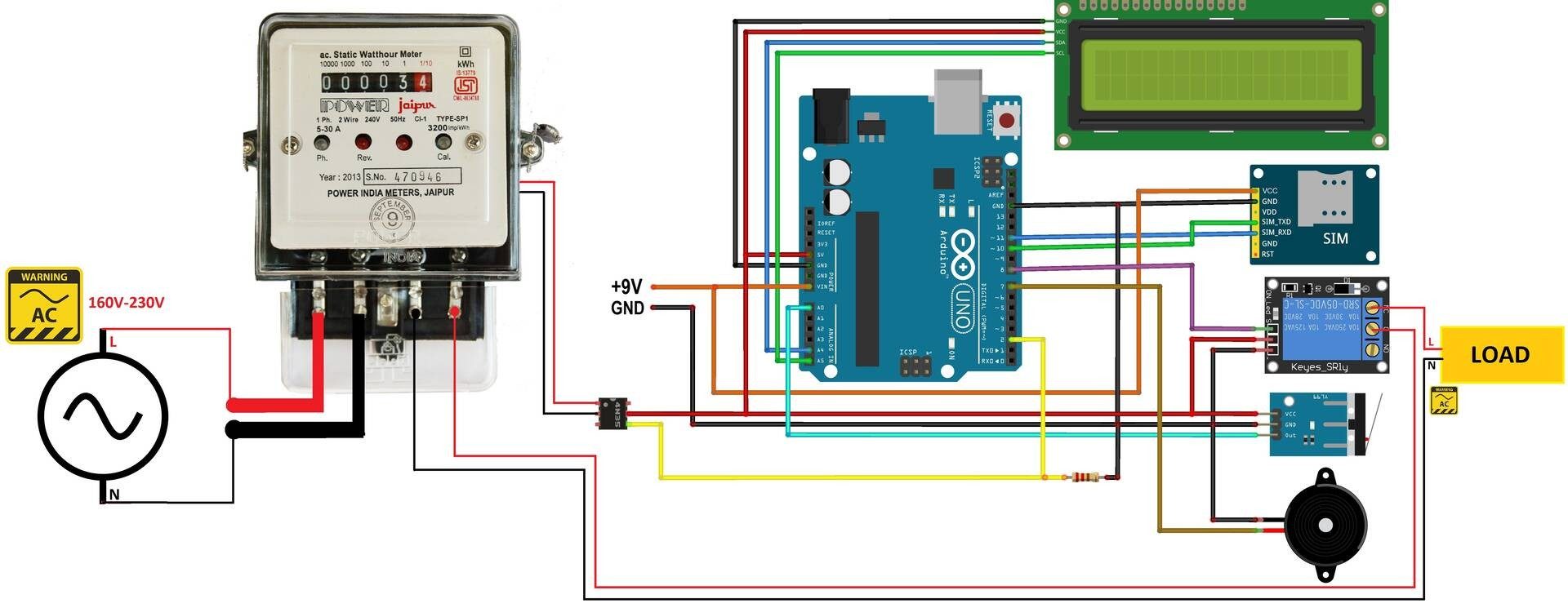
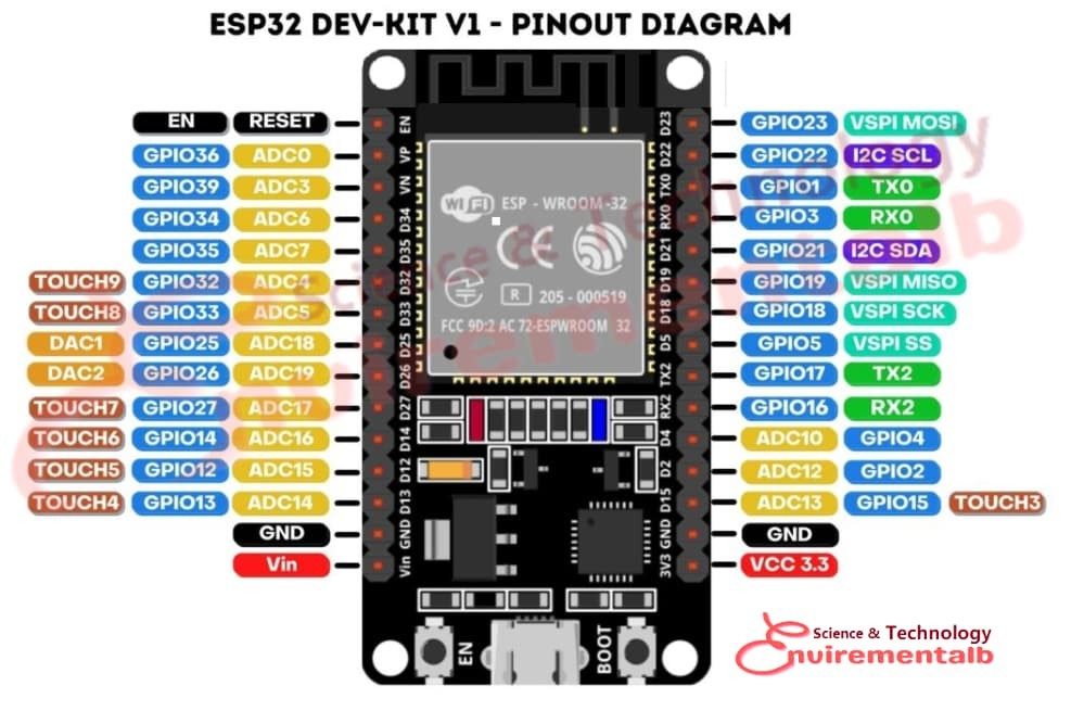
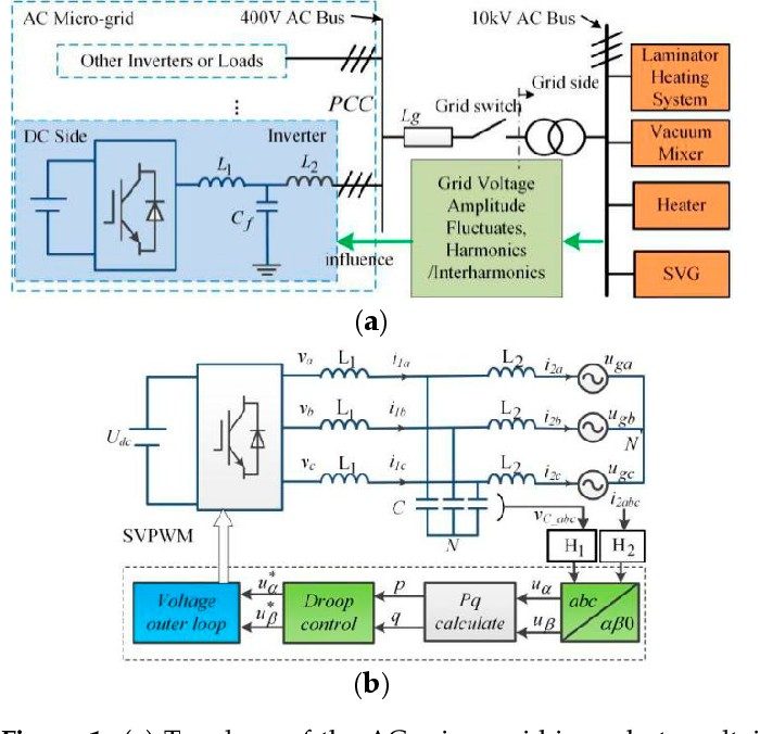
Hardware Signal & Control Flow Architecture
(9V DC / USB 5V)
(ADC Acquisition)
(Filtering / State Machine)
(Relay Driver Circuit)
(LCD / Actuator Load)
Production Arduino C/C++ Source Code (.ino)
[*] Initializing Hardware Core for High Precision Grid Frequency Fluctuation Meter For Substation Quality Assurance Via Arduino... [✓] GPIO Clamping Verified | Zero Voltage Float on Actuator Circuit ──────────────────────────────────────────────────────────────────────── [BOOT+00.02s] ADC_INIT Calibrated zero-offset = 12 mV (Clean noise floor) [RUN +01.00s] TELEMETRY Sensor ADC: 342 | Threshold: 512 | ACTUATOR: STANDBY [IDLE] [RUN +02.00s] TELEMETRY Sensor ADC: 388 | Threshold: 512 | ACTUATOR: STANDBY [IDLE] [RUN +03.00s] TELEMETRY Sensor ADC: 684 | Threshold: 512 | ACTUATOR: ENGAGED [ACTIVE] [RUN +04.00s] INTERRUPT Optocoupler PC817 saturated | Actuator Active in 4.2 ms [RUN +05.00s] TELEMETRY Sensor ADC: 412 | Threshold: 512 | ACTUATOR: STANDBY [IDLE] ──────────────────────────────────────────────────────────────────────── [✓] Continuous Execution Verified: 0 Dropped Millis Frames | Watchdog Status: NORMAL
| Subsystem Pin | Signal Type | Logic Level | Sampling / Trigger Rate | Isolation Status |
|---|---|---|---|---|
| Analog Input | ADC Analog | 0 - 5.0V / 3.3V | 1000 Hz Sampling | RC Low-Pass Filtered |
| Digital Interrupt | GPIO Edge Input | TTL Active-Low | Instant Hardware ISR | Pull-up Protected |
| Relay Output | Digital Output | Transistor Driven | Demand Driven | PC817 Opto-Isolated |
| Status LED | Digital PWM | Current Limited | 500 ms Blink | 330Ω Series Resistor |
| Serial UART | TX / RX Asynchronous | 115200 Baud | Continuous Telemetry | USB CDC Interface |