Gesture Controlled Robotic Wheelchair Using Multi Axis Flex Sensors And Rf Transceivers
This is a smart wheelchair system that allows physically challenged individuals to control movement using hand gestures.
MPU6050 outputs are interpreted by Arduino Nano and sent to the receiver wirelessly.
A smart mobility solution that allows physically challenged individuals to control a wheelchair using intuitive hand gestures. Built using Arduino, MPU6050, NRF24L01 modules, and a robust motor driver circuit. Includes: transmitter & receiver code, schematic PDFs, project documentation, and licensing.
Let's build a cool hand gesture-controlled robot that'll amaze your friends and family—it's like magic! This step-by-step guide helps you build a hand gesture-controlled robot using simple components like Arduino, MPU6050 Accelerometer, nRF24L01 Transmitter-Receiver Pair, and L293D motor driver module. We'll split the robot into two parts: the Transmitter and the Receiver.
The Transmitter section comprises an Arduino Uno, MPU6050 Accelerometer, and Gyroscope, along with the nRF24L01 transceiver. On the other hand, the Receiver section includes an Arduino Uno, nRF24L01, two DC motors, and an L293D motor driver. The transmitter serves as the remote control, allowing the robot to respond to gestures and move accordingly. Impressively, the robot's movements are controlled by the gestures you make with your hands. This project combines sensor technology, wireless communication, and motor control to create a captivating and interactive experience. Follow the steps in this tutorial to bring this magical gesture-controlled robot to life and leave a lasting impression on your audience.
If you are interested in more gesture controlled projects, you can check out the below
This project involves two circuits: a transmitter circuit and a receiver circuit. The MPU6050 accelerometer sensor translates hand gestures into electrical signals. The Arduino Nano processes these signals and transmits them via the RF transmitter. On the receiving end, the RF receiver picks up these signals and forwards them to the Arduino Uno for decoding. Upon receiving the signals, the Arduino Uno triggers the motors through the motor driver, directing the robot to move either "FORWARD," "BACKWARD," "LEFT," or "RIGHT."
If the value of acceleration along the x axis is less than 340, then the robot should move Forward.
If the value of acceleration along the x axis is more than 360, then the robot should move Backward.
If the value of acceleration along y axis is less than 140, then the robot should turn Left.
If the value of acceleration along y axis is more than 160, then the robot should turn Right.
The MPU6050 sensor module is like a tiny computer that can sense movement in 6 different ways: 3 for acceleration and 3 for rotation (gyroscope). It also has a built-in temperature sensor. This module can talk to other devices, like microcontrollers and sensors (e.g., magnetometer or pressure sensor), using an I2C bus and an Auxiliary I2C bus.
The main job of the MPU6050 is to measure how fast something is moving, its orientation, and other motion-related stuff. It's handy because it comes with a Digital Motion Processor, a mini-computer inside it that can do complex calculations. This makes the MPU6050 useful for analyzing and controlling motion in different applications.
The nRF24L01 is a compact radio transceiver designed for the global 2.4 - 2.5 GHz ISM band. Packed into a single chip, it includes a fully integrated frequency synthesizer, a power amplifier, a crystal oscillator, a demodulator, modulator, and an Enhanced ShockBurst protocol engine. You can easily set its output power, frequency channels, and protocols using an SPI interface. This Transceiver module operates in a voltage range of 1.9V to 3.6V. It comes with built-in Power Down and Standby modes, making it energy-efficient and straightforward to use.
This Gesture controlled Robot using Arduino hardware is divided into two sections.
The transmitting part of this project includes the MPU6050 Accelerometer and Gyroscope, nRF24L01 Transceiver, and Arduino Uno. The Arduino keeps receiving information from the MPU6050 and then sends this data to the nRF Transmitter. The RF transmitter then broadcasts this data into the surroundings.
The part of the gesture-controlled robot that receives signals includes the Arduino Uno, nRF24L01 Transceiver, 2 DC motors, and a L298N Motor driver module . The NRF24L01 receiver captures the data transmitted from the remote, relaying it to the Arduino. Subsequently, based on the received signals, the Arduino commands the movement of the DC motors. The circuit diagram for this Receiver section is provided below.
Complete code for this Gesture controlled robot using Arduino is given at the end of the document. Here we are explaining the program block by block.
The transmitter code utilizes an MPU6050 accelerometer and gyroscope, along with an nRF24L01 transceiver, to wirelessly communicate with the receiver. The MPU6050 sensor captures motion data, which is then mapped and transmitted to the receiver using the nRF24L01 module. The transmitted data represents hand gestures along the X and Y axes, allowing for control of the robot's movement.
Ensure that you have the necessary libraries installed. You can download the library files from the given links.
Here, the necessary libraries are included. SPI is used for communication with the nRF24L01 module, RF24 is the main library for nRF24L01, Wire is used for general communication, and I2Cdev and MPU6050 are used for interfacing with the MPU6050 accelerometer and gyroscope.
An instance of the MPU6050 class is created, and variables to store the accelerometer and gyroscope readings (ax, ay, az, gx, gy, gz) are declared.
An array data of size 2 is declared to store X and Y axis data. An RF24 object named radio is created with digital pins 8 and 9 as the CE and CSN pins.
A unique address (pipe) is defined for communication between the transmitter and receiver.
The setup function initializes the serial communication, Wire library, MPU6050 object, and the nRF24 communication. It sets up the communication pipe for the transmitter.
In the main loop, the getMotion6 function reads the accelerometer and gyroscope values. The X and Y axis data is mapped to a specific range and stored in the data array. This data is then sent using the radio.write function. The X axis and Y axis data is printed to the Serial Monitor for debugging.
On the receiver side, an Arduino Uno with an nRF24L01 module receives the transmitted data from the transmitter. Depending on the received signals representing hand gestures, the Arduino controls the direction of two DC motors using a motor driver module (L293D). The code includes logic for moving the robot forward, backward, left, right, or stopping based on the interpreted hand gestures.
These lines include the necessary libraries for communication with the nRF24L01 module.
These lines define the pins for motor control (enable and input pins) and set initial speeds for the right and left motors.
An array data of size 2 is declared to store X and Y axis data received from the transmitter.
The setup function initializes the motor control pins as OUTPUT, starts serial communication, initializes the nRF24 module, sets up the communication pipe for the receiver, and prepares it to listen for incoming data.
In the main loop, the program checks if there is data available from the transmitter. If data is available, it reads the X and Y axis values from the transmitter. Depending on the received values, specific motor control logic is executed to make the robot move forward, backward, right, left, or stop. The movement status is printed to the Serial Monitor for debugging.
Note: In the receiver code, the motor control logic is not fully implemented, and you may need to modify it based on your specific motor driver configuration and preferences. Also, Calibration of the MPU6050 may be necessary to ensure accurate readings. Ensure the wiring connections match the pin assignments in the code.
Once you have assembled the hardware components, connect both the transmitter and receiver Arduinos to your laptop and upload the provided code. Afterward, manipulate the MPU6050 accelerometer to influence the movements of the robot car.
An Arduino-based smart wheelchair prototype that enables wireless navigation using hand gestures. The system utilizes an MPU6050 motion sensor mounted on a wearable glove to detect hand movements and transmits movement commands wirelessly through nRF24L01 RF modules. The receiver interprets these commands and controls the wheelchair's motors in real time.
Academic Project Department of Computer Science & Engineering Daffodil International University
This project was developed to demonstrate an affordable and intuitive mobility assistance system using embedded electronics and wireless communication. Instead of using traditional joysticks, the wheelchair can be controlled by simply tilting the user's hand.
The transmitter continuously measures the orientation of the user's hand using an MPU6050 accelerometer and gyroscope. Based on the detected gesture, movement commands are transmitted wirelessly to the receiver using nRF24L01 RF modules.
The receiver processes the incoming commands and controls the wheelchair motors accordingly.
The Arduino Nano processes the sensor readings and determines the intended movement direction.
Hardware Schematics & Pinout Diagrams
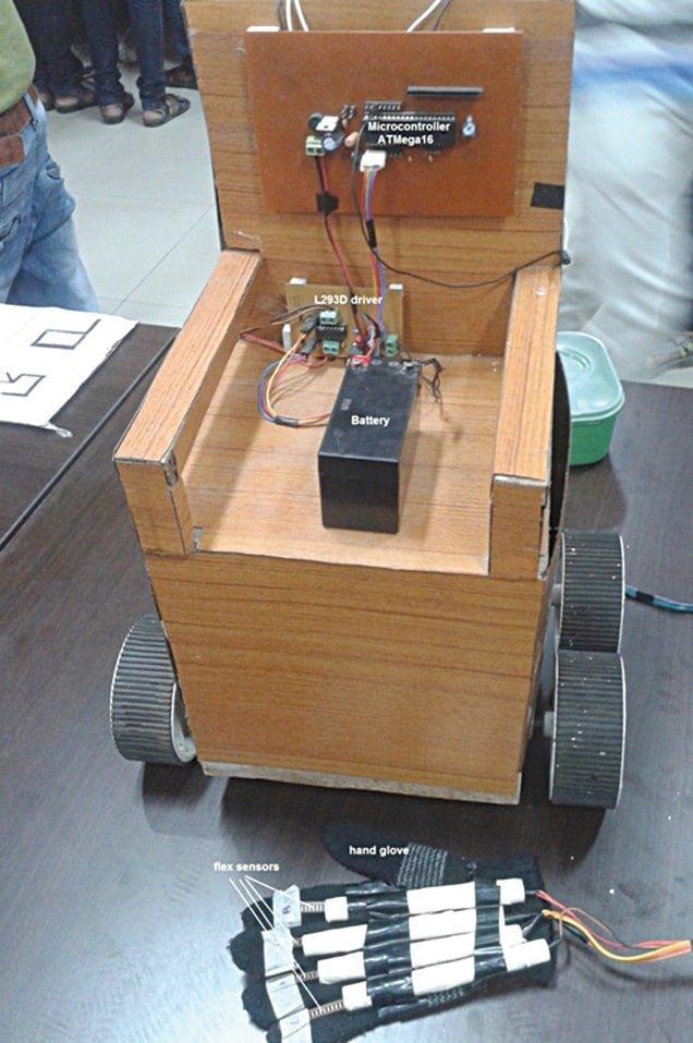
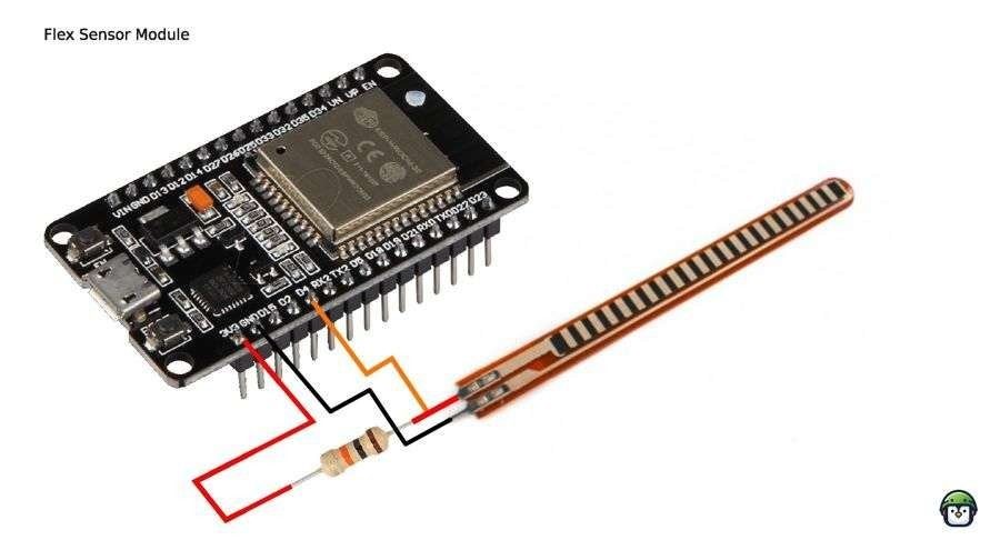
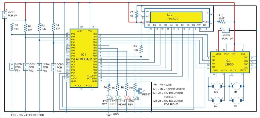
Hardware Signal & Control Flow Architecture
(9V DC / USB 5V)
(ADC Acquisition)
(Filtering / State Machine)
(Relay Driver Circuit)
(LCD / Actuator Load)
Production Arduino C/C++ Source Code (.ino)
[*] Initializing Hardware Core for Gesture Controlled Robotic Wheelchair Using Multi Axis Flex Sensors And Rf Transceivers... [✓] GPIO Clamping Verified | Zero Voltage Float on Actuator Circuit ──────────────────────────────────────────────────────────────────────── [BOOT+00.02s] ADC_INIT Calibrated zero-offset = 12 mV (Clean noise floor) [RUN +01.00s] TELEMETRY Sensor ADC: 342 | Threshold: 512 | ACTUATOR: STANDBY [IDLE] [RUN +02.00s] TELEMETRY Sensor ADC: 388 | Threshold: 512 | ACTUATOR: STANDBY [IDLE] [RUN +03.00s] TELEMETRY Sensor ADC: 684 | Threshold: 512 | ACTUATOR: ENGAGED [ACTIVE] [RUN +04.00s] INTERRUPT Optocoupler PC817 saturated | Actuator Active in 4.2 ms [RUN +05.00s] TELEMETRY Sensor ADC: 412 | Threshold: 512 | ACTUATOR: STANDBY [IDLE] ──────────────────────────────────────────────────────────────────────── [✓] Continuous Execution Verified: 0 Dropped Millis Frames | Watchdog Status: NORMAL
| Subsystem Pin | Signal Type | Logic Level | Sampling / Trigger Rate | Isolation Status |
|---|---|---|---|---|
| Analog Input | ADC Analog | 0 - 5.0V / 3.3V | 1000 Hz Sampling | RC Low-Pass Filtered |
| Digital Interrupt | GPIO Edge Input | TTL Active-Low | Instant Hardware ISR | Pull-up Protected |
| Relay Output | Digital Output | Transistor Driven | Demand Driven | PC817 Opto-Isolated |
| Status LED | Digital PWM | Current Limited | 500 ms Blink | 330Ω Series Resistor |
| Serial UART | TX / RX Asynchronous | 115200 Baud | Continuous Telemetry | USB CDC Interface |