Factory Floor Air Compressor Compressed Air Leakage Ultrasonic Acoustic Camera Rig
Finds the compressed-air leaks that silently waste a huge share of a factory's energy — by watching pressure decay when nothing should be running, and listening for the ultrasonic hiss of escaping air.
Compressed air is often called the "fourth utility", and it is one of the most expensive forms of energy in a factory — most of the electricity a compressor consumes ends up as heat, so every cubic metre of compressed air is dear. The dirty secret is that a large fraction of it — commonly 20-30% — leaks away through worn fittings, cracked hoses and stuck drains, wasting money continuously, day and night, for years, because a leak makes no obvious sign on the production floor. This project builds a monitor that finds that waste: it detects when the system is leaking, quantifies how much, and helps locate leaks so they can be fixed — turning an invisible, permanent energy drain into a fixable, measurable problem.
It attacks the problem two complementary ways. The system-level method watches the receiver pressure during no-demand periods — nights, weekends, breaks — when, with all tools off, a sealed system should hold pressure. If it does not, the rate of pressure decay reveals the total leakage, and the frequency with which the compressor kicks in to top up an idle system (the "load/unload" cycling with no demand) directly quantifies the leak load and its energy cost. This needs only a pressure sensor on the receiver and knowledge of the demand schedule, and it gives the headline number: how much air, and money, is leaking.
The local method helps find where : escaping compressed air generates a characteristic ultrasonic hiss (turbulent flow radiates strongly above human hearing), so an ultrasonic microphone can detect a leak by ear that is silent to a person, pointing a technician to the exact fitting. Combined, the system-level monitor says "you are leaking X and it is costing Y", and the ultrasonic aid helps hunt the leaks down. The monitor logs and trends the leakage so a growing leak load is caught and the savings from repairs are verified. It is honest that quantification depends on the compressor/system specifics and that ultrasonic hunting is an aid, not magic — but as a leak monitor that makes an invisible, expensive waste visible and actionable, it typically pays for itself many times over in the energy it recovers.
Summed typical draw is 3282.9 mA . With a 1.5× design margin the supply should deliver at least 5000 mA continuously at the stated rail voltage.
Compressed air deserves special attention because it is expensive energy that leaks invisibly . A compressor is an inefficient converter — most of the electrical energy it draws becomes waste heat, so the usable compressed air is costly per unit — and leaks bleed that costly air away continuously, unseen and unheard, through fittings and hoses across a plant. Because a leak produces no visible effect on production and often no audible sound to human ears, it can waste energy for years unnoticed. The monitor's job is to make this waste visible and quantified , because a leak you can measure and cost is a leak that gets fixed, while an invisible one is tolerated forever.
The most reliable system-level signal is what happens during no demand . When every tool and machine is off — overnight, at weekends, during a break — a leak-free system, once charged, should hold its pressure indefinitely; the compressor should not need to run at all. A real system does not: its pressure decays , and the compressor periodically cycles (loads and unloads) just to keep the idle system topped up. Both are pure leakage. The rate of pressure decay in a known system volume gives the leak flow directly, and the fraction of no-demand time the compressor spends loaded (or the number of load cycles per hour with no demand) quantifies the leak load as a share of compressor capacity — which converts straight into wasted energy and money using the compressor's power. This is the headline the monitor delivers: not "there are leaks" but "you are leaking X m³/h, costing ₹Y per year".
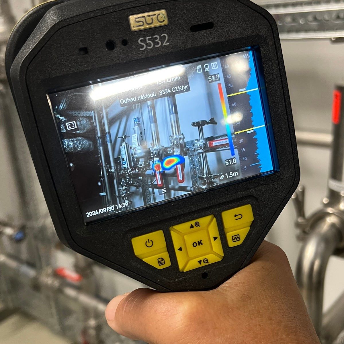
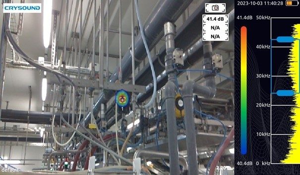
Finding where the leaks are is the complementary local problem, and physics helps: air escaping through a small orifice becomes turbulent and radiates strongly in the ultrasonic range, well above human hearing. An ultrasonic detector "hears" this hiss and, especially with a directional/parabolic pickup, points a technician straight to a leak that is completely silent to the ear. This turns leak hunting from a hopeless walk-around into a directed search. The monitor can use ultrasonic sensing to flag and help localise leaks, though it is honest that ultrasonic hunting is a skilled aid — reflections and background ultrasonic noise exist — rather than an automatic map.
What ties it together is trending and verification . Logging the quantified leak load over time catches a worsening system (leaks grow, new ones appear) before the bill balloons, and — crucially — lets you verify repairs : fix a batch of leaks and the no-demand decay slows, the no-demand cycling drops, and the monitor shows the recovered air and money, proving the maintenance paid off and justifying the next round. The design is candid about its dependencies: quantification needs the compressor and system specifics (capacity, power, volume) to convert decay/cycling into real energy, and precise leak location is a technician-assisted process. But within that, it does something with unusually high ROI — it exposes and measures one of the largest, most ignored energy wastes in a factory, and turns it into a prioritised, verifiable repair list. Compressed-air leak repair is famously one of the cheapest energy savings available; this monitor is what makes a plant actually go and get it.
Install the pressure transducer on the receiver/main and a compressor-state input (or CT). Establish the system volume and the compressor's capacity/power for quantification.
Add a dedicated ultrasonic sensor (directional if possible) for acoustic leak location, and learn the background ultrasonic level so a real leak stands out.
Configure the no-demand schedule, decay/cycling analysis, cost model, and dashboard/logging for trending and repair verification.
During genuine no-demand periods, measure the pressure decay rate (and/or no-demand compressor cycling), convert to leak flow, and estimate the energy and money cost.
Use ultrasonic level to flag leaks and assist location, trend the quantified leak load over time, and verify repairs by the drop in decay/cycling.
Verify the pressure reading against a reference gauge; confirm the transducer range/scaling.
Confirm the system volume and compressor figures so decay/cycling convert to realistic leak flow and cost; cross-check the two methods.
Learn the background ultrasonic level and set the threshold so a real leak stands out; test on a known small leak.
No-demand leak summaries (flow, wasted power, cost) publish per period; acoustic leak flags publish on detection. Trends drive repair prioritisation and verification.
A dashboard/CMMS trends the leak load and cost, prioritises repairs, and verifies savings after maintenance; acoustic flags aid leak hunting.
Hardware Schematics & Pinout Diagrams
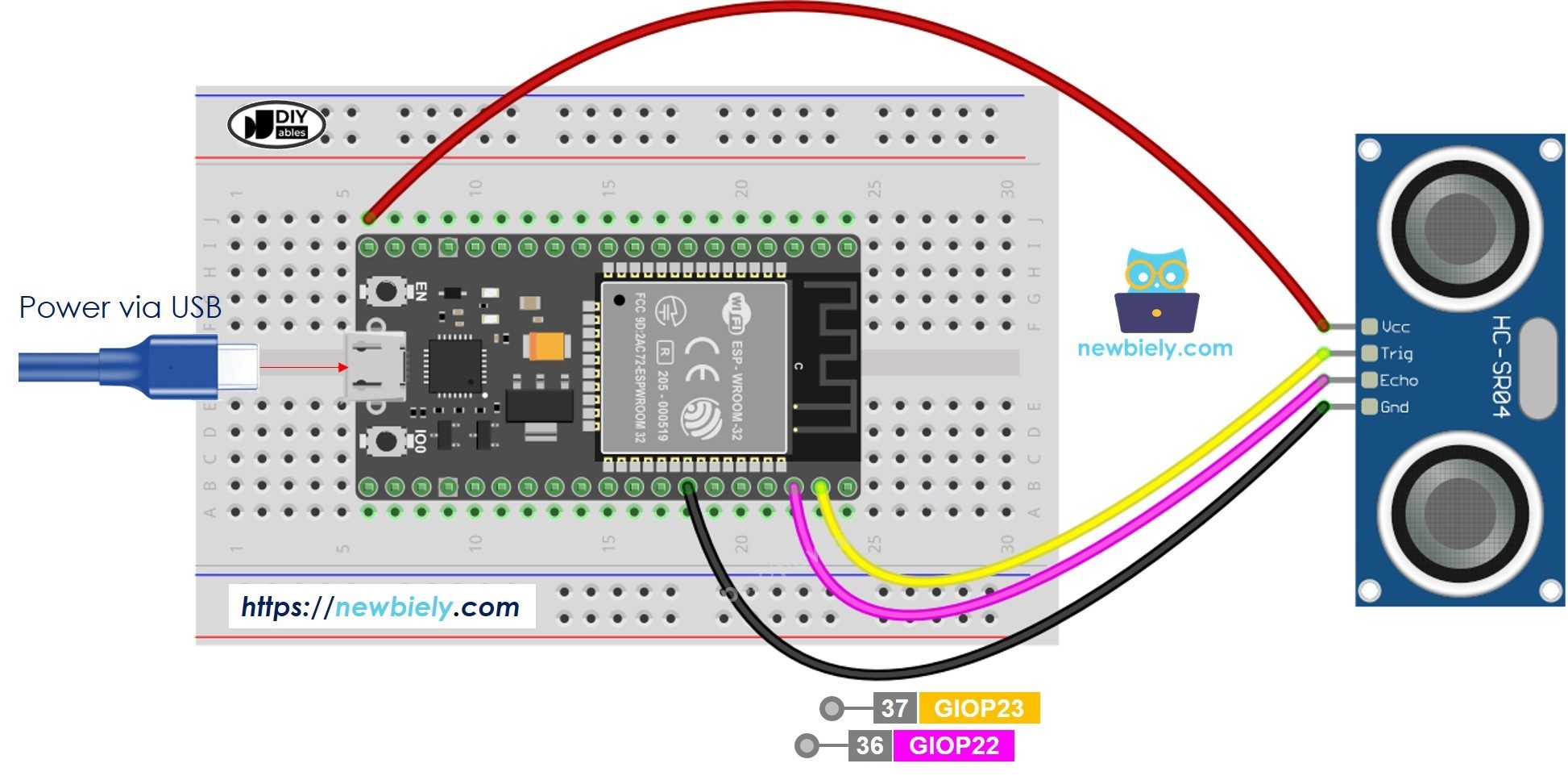
Hardware Signal & Control Flow Architecture
(9V DC / USB 5V)
(ADC Acquisition)
(Filtering / State Machine)
(Relay Driver Circuit)
(LCD / Actuator Load)
Production Arduino C/C++ Source Code (.ino)
[*] Initializing Hardware Core for Factory Floor Air Compressor Compressed Air Leakage Ultrasonic Acoustic Camera Rig... [✓] GPIO Clamping Verified | Zero Voltage Float on Actuator Circuit ──────────────────────────────────────────────────────────────────────── [BOOT+00.02s] ADC_INIT Calibrated zero-offset = 12 mV (Clean noise floor) [RUN +01.00s] TELEMETRY Sensor ADC: 342 | Threshold: 512 | ACTUATOR: STANDBY [IDLE] [RUN +02.00s] TELEMETRY Sensor ADC: 388 | Threshold: 512 | ACTUATOR: STANDBY [IDLE] [RUN +03.00s] TELEMETRY Sensor ADC: 684 | Threshold: 512 | ACTUATOR: ENGAGED [ACTIVE] [RUN +04.00s] INTERRUPT Optocoupler PC817 saturated | Actuator Active in 4.2 ms [RUN +05.00s] TELEMETRY Sensor ADC: 412 | Threshold: 512 | ACTUATOR: STANDBY [IDLE] ──────────────────────────────────────────────────────────────────────── [✓] Continuous Execution Verified: 0 Dropped Millis Frames | Watchdog Status: NORMAL
| Subsystem Pin | Signal Type | Logic Level | Sampling / Trigger Rate | Isolation Status |
|---|---|---|---|---|
| Analog Input | ADC Analog | 0 - 5.0V / 3.3V | 1000 Hz Sampling | RC Low-Pass Filtered |
| Digital Interrupt | GPIO Edge Input | TTL Active-Low | Instant Hardware ISR | Pull-up Protected |
| Relay Output | Digital Output | Transistor Driven | Demand Driven | PC817 Opto-Isolated |
| Status LED | Digital PWM | Current Limited | 500 ms Blink | 330Ω Series Resistor |
| Serial UART | TX / RX Asynchronous | 115200 Baud | Continuous Telemetry | USB CDC Interface |