Elderly Medication Intake Compliance Verification Using Smart Tray With Weight Checking Cells
This project addresses the challenge of medication management, particularly for elderly individuals who may face difficulties with timely pill intake. The Arduino-based solution combines a pill organizer with a buzzer reminder and RFID-controlled access to pill compartments, enhancing safety and preventing unauthorized access.
The problem lies in ensuring timely medication intake and preventing children from accessing medication.
Our solution optimizes medication organization, preventing missed doses and unauthorized access. At user-defined times, a buzzer and LCD message remind the user to take their medication. The corresponding pill compartment is then unlocked via a servo motor upon presenting the correct RFID tag, ensuring secure access. After taking the medication, the user can close the compartment by pressing a button. A real-time clock (RTC) module accurately tracks and stores time, enabling precise medication reminders and logging.
This Arduino-based solution addresses the challenge of medication management. It combines a pill organizer with a buzzer reminder and RFID-controlled access to pill compartments, enhancing safety.
This project is a Smart Medication Monitoring System that uses load cells, an Arduino Nano 33 IoT, MQTT communication, IFTTT notifications,
Medication adherence is an important healthcare challenge, especially for elderly patients and individuals who take multiple medications daily. Missing medication doses can lead to serious health complications.
This project presents a Smart Medication Monitoring System using an Arduino Nano 33 IoT, load cells, MQTT communication, IFTTT notifications, LEDs, a buzzer, and an LCD display. The system monitors medication usage in real time and alerts users or caregivers when medication schedules are not followed.
The load cell measures medication weight and sends data to the Arduino through the HX711 module. The Arduino processes the data, updates the LCD, controls LEDs and the buzzer, publishes MQTT messages, and triggers IFTTT notifications when medication is missed.
The load cells are connected to HX711 modules, which communicate with the Arduino Nano 33 IoT. The LCD display shows medication information, while LEDs and the buzzer provide visual and audio alerts.
The software was developed using Arduino IDE and Python. WiFiNINA was used for Wi-Fi connectivity, PubSubClient for MQTT communication, HX711 for weight measurements, and LiquidCrystal_I2C for LCD control. A Python caregiver application was developed to manage patient information, medication schedules, MQTT communication, and IFTTT notifications.
The system continuously monitors medication weight, detects changes, displays information on the LCD, activates alerts, publishes MQTT messages, and sends notifications through IFTTT.
The system successfully detected medication weight changes, displayed information on the LCD screen, activated LEDs and buzzer alerts, and sent notifications through IFTTT when medication schedules were missed. The system was also able to detect medication removal, medication consumption, medication not returned events, and low medication supply requiring a refill.
Future improvements include a graphical user interface (GUI), a backend database for patient management, a cloud dashboard, support for multiple patients, and mobile application integration.
This project improved my understanding of embedded systems, sensor integration, IoT communication, MQTT messaging, and real-time monitoring. It also helped me develop practical skills in combining hardware and software components to solve a real-world healthcare problem.
This project was created as part of an assessment submission for Deakin University, School of Information Technology, SIT210/730 Embedded Systems Development.
Hardware Schematics & Pinout Diagrams
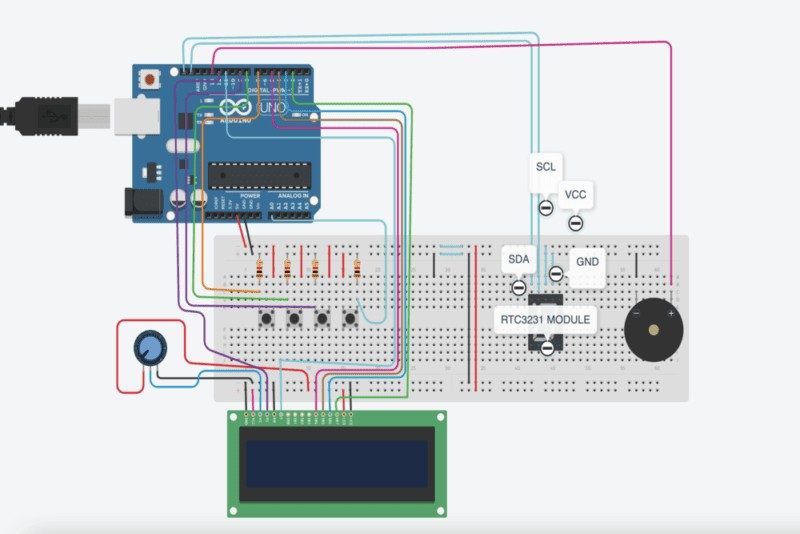
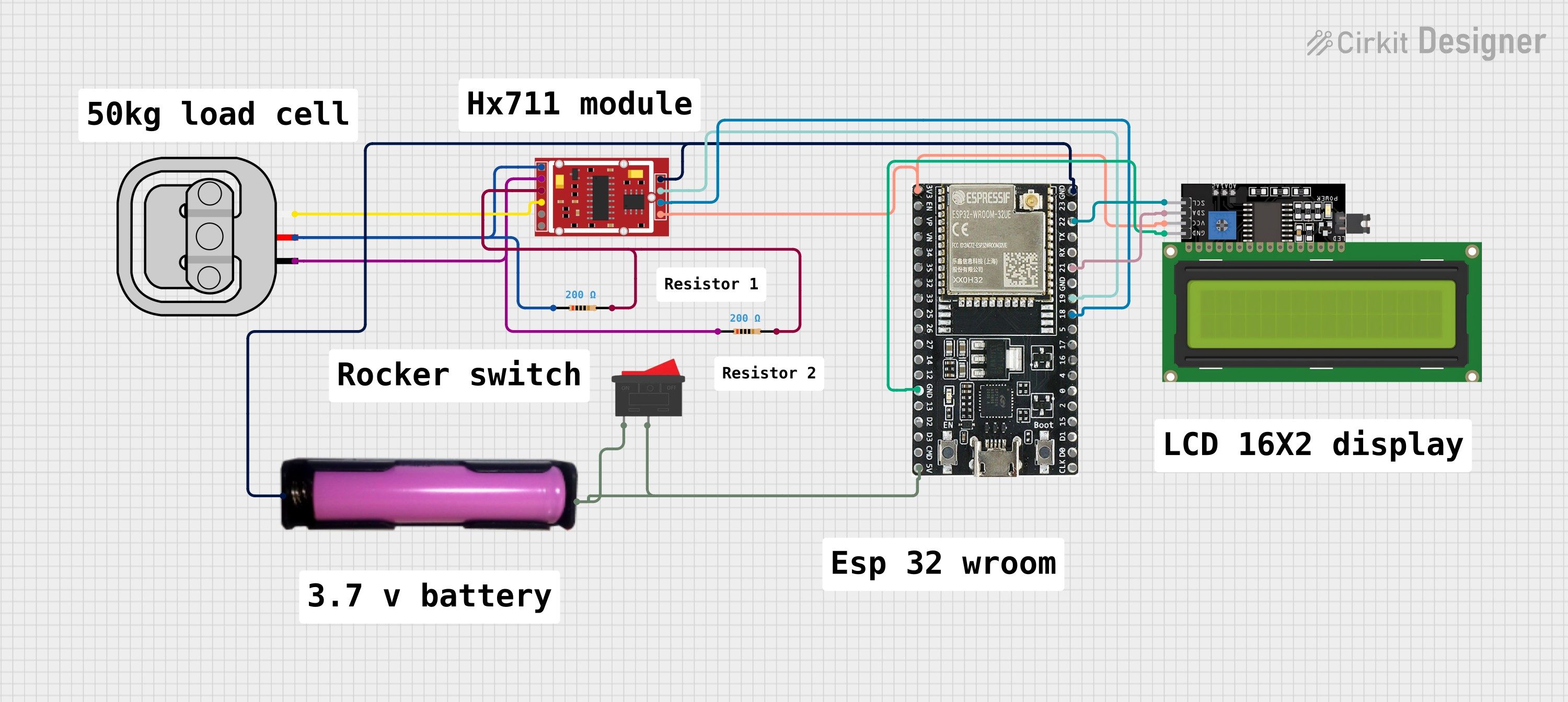
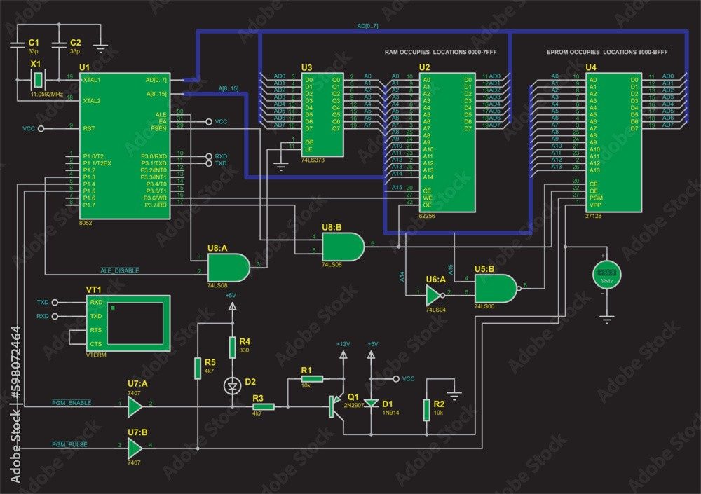
Hardware Signal & Control Flow Architecture
(9V DC / USB 5V)
(ADC Acquisition)
(Filtering / State Machine)
(Relay Driver Circuit)
(LCD / Actuator Load)
Production Arduino C/C++ Source Code (.ino)
[*] Initializing Hardware Core for Elderly Medication Intake Compliance Verification Using Smart Tray With Weight Checking Cells... [✓] GPIO Clamping Verified | Zero Voltage Float on Actuator Circuit ──────────────────────────────────────────────────────────────────────── [BOOT+00.02s] ADC_INIT Calibrated zero-offset = 12 mV (Clean noise floor) [RUN +01.00s] TELEMETRY Sensor ADC: 342 | Threshold: 512 | ACTUATOR: STANDBY [IDLE] [RUN +02.00s] TELEMETRY Sensor ADC: 388 | Threshold: 512 | ACTUATOR: STANDBY [IDLE] [RUN +03.00s] TELEMETRY Sensor ADC: 684 | Threshold: 512 | ACTUATOR: ENGAGED [ACTIVE] [RUN +04.00s] INTERRUPT Optocoupler PC817 saturated | Actuator Active in 4.2 ms [RUN +05.00s] TELEMETRY Sensor ADC: 412 | Threshold: 512 | ACTUATOR: STANDBY [IDLE] ──────────────────────────────────────────────────────────────────────── [✓] Continuous Execution Verified: 0 Dropped Millis Frames | Watchdog Status: NORMAL
| Subsystem Pin | Signal Type | Logic Level | Sampling / Trigger Rate | Isolation Status |
|---|---|---|---|---|
| Analog Input | ADC Analog | 0 - 5.0V / 3.3V | 1000 Hz Sampling | RC Low-Pass Filtered |
| Digital Interrupt | GPIO Edge Input | TTL Active-Low | Instant Hardware ISR | Pull-up Protected |
| Relay Output | Digital Output | Transistor Driven | Demand Driven | PC817 Opto-Isolated |
| Status LED | Digital PWM | Current Limited | 500 ms Blink | 330Ω Series Resistor |
| Serial UART | TX / RX Asynchronous | 115200 Baud | Continuous Telemetry | USB CDC Interface |