Edge Based Acoustic Anomaly Detection For 3D Printer Extruder Filament Grinding
MYWAI™ VILMA™ is designed to bring human-like learning to robots via one-shot demonstration
Schweizer’s approach is to use the UNO Q and a camera to detect anomalies , rather than specific problems. It doesn’t look for spaghetti failure or clogging. Instead, it looks for a normal print. Anything abnormal gets flagged. That dramatically reduces the amount of training data required and accounts for all visible issues, whether they were anticipated and trained for or not.
The hardware required for this includes an UNO Q (4GB model), an Arduino ® UNO ™ Media Carrier , an V2-style IMX219 camera module, and a custom-printed mount with fasteners. The goal with that mount is to point the camera at the hot end and below, so it will likely require customization to fit the 3D printer model in question.
All of the magic happens thanks to the FOMO-AD anomaly model from Edge Impulse, implemented through Arduino App Lab . That requires training on images of normal prints and Schweizer explains how it is easy to collect those automatically during print jobs. By keeping the image resolution low (632×480), the overhead remains minimal and the model efficient.
As Schweizer points out, an overeager watchdog is worse than not having a watchdog at all. For that reason, Schweizer built his app so that it only automatically pauses a print if at least three out of the last four images show an anomaly. When that is the case, it pauses the job through the Moonraker API (standard for Klipper-based systems). For those who don’t use Klipper, it is possible to integrate the watchdog into Octoprint or other control software. It also sends an MQTT message compatible with Home Assistant for notifications and hosts a webpage where the status is visible.
Anyone who has left a long 3D print running overnight knows the risk: if the part comes loose from the bed, the printer keeps extruding into thin air for hours, and in the morning there is a tangle of filament on the bed. That is exactly what we built an AI print watchdog against over the past few weeks: a camera, a board for under 100 euros and a model trained exclusively on images of successful prints. It detects failed prints, sends a push notification with a photo as evidence to your phone and pauses the print if you want it to. All of the inference runs as Edge AI directly on an Arduino UNO Q next to the printer – no cloud, no subscription, and not a single image leaves the workshop.
The project was set up as an open experiment from the start: is a thumbnail-sized chip enough for a task that commercial services hand to their cloud data centres? This is the short version of the five-part series (as of 2 September 2026): what the system can do, how it is built, which numbers came out of it and where it still falls short. The step-by-step instructions live in the individual parts, which are linked where they belong.
The Arduino team featured the project on the official Arduino Blog on 14 September 2026.
An FDM printer does not notice when its print fails. If the part comes loose from the bed in hour three, the nozzle clogs or the filament starts stringing, it keeps printing regardless. The result is a tangle of filament the community calls “spaghetti”: it costs material and hours, and in the worst case it encases the hotend. It is noticed latest on exactly those prints that run overnight or unattended during the day.
The watchdog closes that gap. It looks at the print bed every 15 seconds, reports a failed print within a minute via push notification to your phone – with a photo in which the suspicious image regions are marked – and can pause the printer on its own if you allow it. A missed failure costs a night of spaghetti and a spool of filament; an alarm costs a glance at your phone.
Without AI this is hard to solve: a print looks different every minute. The bed moves, the head comes and goes, the object grows, the filament changes colour. A motion detector or a fixed brightness value cannot tell “healthy” from “broken”. An anomaly model can, because it has seen thousands of images of normal prints and reports everything that deviates from them: spaghetti, a detached part, a strand across the bed.
A print watchdog is a textbook case for Edge AI. The task is narrow – does the print bed look normal? –, the data is produced right at the device, and millisecond real time is not needed: one image every 15 seconds is enough, because a spaghetti tangle takes minutes to grow. At the same time, nobody wants to stream a constant feed of workshop photos to someone else’s server or pay a subscription for it.
The Arduino UNO Q suits this role because it combines two worlds on one board: a Debian Linux on the Qualcomm processor that runs the AI model, and a classic microcontroller for real-time jobs such as the LED matrix that serves as the alarm light at the printer. Arduino’s App Lab packages both into an app made of ready-made building blocks, the “bricks” , and Edge Impulse lists the UNO Q as an official target device – so the model export fits without any tinkering.
The watchdog works in a simple cycle. The UNO Q asks the printer via the Moonraker API whether a print is running. If so, it grabs a camera frame, runs it through the anomaly model and gets a score back. If three of the last four checks are above the alarm threshold, it raises the alarm: red LED matrix, evidence photo with marked regions, an MQTT message to Home Assistant and, optionally, a pause command to the printer. All of this runs on the board. Home Assistant is only the route for the push notification to your phone – how to make your printer network-capable with Klipper and Moonraker is covered in this article .
The obvious route – training a model on thousands of photos of failed prints – fails at the data stage. Nobody deliberately crashes dozens of prints, certainly not on a borrowed printer. So the watchdog relies on anomaly detection with FOMO-AD, the visual anomaly model from Edge Impulse. It learns exclusively what a normal print looks like and reports everything that deviates from it. The training images accumulate by themselves with every successful print; you only need a handful of failure images to set the alarm threshold.
The principle has a flip side that shaped the whole project: FOMO-AD does not learn “spaghetti”, it learns “this is what it normally looks like here”. Camera position, framing, focus and lighting are part of the model. Every mount that shifts and every new lamp in the room invalidates the dataset together with the model. For anyone rebuilding this: fix the hardware first, then collect.
The shopping list is short: the Arduino UNO Q, the UNO Media Carrier with two CSI camera connectors and an IMX219 camera in the V2 form factor – in our case an Arducam NoIR module. The carrier only supports IMX219 sensors; a Camera Module 3 does not work. A USB webcam on a USB-C hub does the job as well.
The case for the UNO Q and the camera mount come out of the 3D printer. The first version was a clamp on the housing edge of the Elegoo Neptune 4 Plus that shifted at the slightest touch in everyday use. In part 5 it gave way to a rigid arm on the Z strut, designed parametrically in FreeCAD, that carries both board and camera. All print files are in the GitHub repository .
Before the camera delivered a single frame, a detour was needed: the standard UNO Q image does not enable the camera subsystem of the Qualcomm chip. On current images there is a switch for it in the App Lab settings (Carriers → Camera0 “type1-2lanes”); on older images you need a custom boot entry with the matching device tree – both are described in part 2 . The camera delivers 632 × 480 pixels; the reserved memory does not allow more. The model only works with 96 × 96 pixels anyway, later 160 × 160.
A GStreamer script saved one frame every ten seconds during each print. After a week of everyday prints there were around 2,600 normal images, plus 20 real stringing images from an unplanned failed print. The upload ran straight from the board via curl to the Edge Impulse ingestion API, with no extra software. Training took five minutes ( part 3 ).
The first test result looked like a write-off: F1 score 0.23. The raw data showed the opposite. All 20 failure images were detected, the normal images had a median score of 26 and 99 percent of them were below 33, the failure images started at 44. Only the default threshold of 27.3 sat right in the middle of the normal distribution. With the threshold at 40 the F1 score stood at 1.00 – and on the side, the model found a strand across the bed that we had overlooked while labelling.
Hardware Schematics & Pinout Diagrams
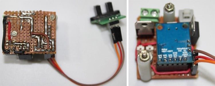
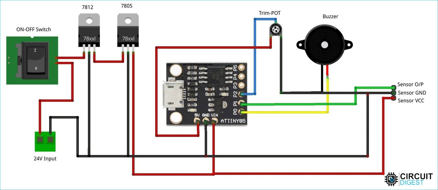
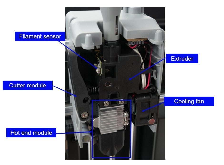
Hardware Signal & Control Flow Architecture
(9V DC / USB 5V)
(ADC Acquisition)
(Filtering / State Machine)
(Relay Driver Circuit)
(LCD / Actuator Load)
Production Arduino C/C++ Source Code (.ino)
[*] Initializing Hardware Core for Edge Based Acoustic Anomaly Detection For 3D Printer Extruder Filament Grinding... [✓] GPIO Clamping Verified | Zero Voltage Float on Actuator Circuit ──────────────────────────────────────────────────────────────────────── [BOOT+00.02s] ADC_INIT Calibrated zero-offset = 12 mV (Clean noise floor) [RUN +01.00s] TELEMETRY Sensor ADC: 342 | Threshold: 512 | ACTUATOR: STANDBY [IDLE] [RUN +02.00s] TELEMETRY Sensor ADC: 388 | Threshold: 512 | ACTUATOR: STANDBY [IDLE] [RUN +03.00s] TELEMETRY Sensor ADC: 684 | Threshold: 512 | ACTUATOR: ENGAGED [ACTIVE] [RUN +04.00s] INTERRUPT Optocoupler PC817 saturated | Actuator Active in 4.2 ms [RUN +05.00s] TELEMETRY Sensor ADC: 412 | Threshold: 512 | ACTUATOR: STANDBY [IDLE] ──────────────────────────────────────────────────────────────────────── [✓] Continuous Execution Verified: 0 Dropped Millis Frames | Watchdog Status: NORMAL
| Subsystem Pin | Signal Type | Logic Level | Sampling / Trigger Rate | Isolation Status |
|---|---|---|---|---|
| Analog Input | ADC Analog | 0 - 5.0V / 3.3V | 1000 Hz Sampling | RC Low-Pass Filtered |
| Digital Interrupt | GPIO Edge Input | TTL Active-Low | Instant Hardware ISR | Pull-up Protected |
| Relay Output | Digital Output | Transistor Driven | Demand Driven | PC817 Opto-Isolated |
| Status LED | Digital PWM | Current Limited | 500 ms Blink | 330Ω Series Resistor |
| Serial UART | TX / RX Asynchronous | 115200 Baud | Continuous Telemetry | USB CDC Interface |