Early Volcanic Ash Plume Detection System Using Solar Irradiance Scattering Measurement
Design a solar radiation meter using Arduino to measure the solar panel’s energy output and irradiance, integrated enhanced performance, and energy management.
// Pin definitions const int currentSensorPin = A1; // Pin for current sensor (ACS712 or Multispan sensor) const int buttonPin = 2; // Pin for calibration button const int decimalPrecision = 2; // Decimal precision for current display
// Variables float mVperAmp = 185; // Calibration constant for the ACS712 5A sensor float current = 0; // Measured current float irradiation = 0; // Calculated solar radiation (W/m²) float powerGenerated = 0; // Power output in watts float accumulatedEnergy = 0; // Accumulated energy in Watt-hours (Wh)
void setup { pinMode(buttonPin, INPUT_PULLUP); // Button for calibration lcd.begin; lcd.backlight; lcd.print("Solar Meter Init"); delay(2000); // Short delay before starting calibration lcd.clear; calibrateSensor; }
void loop { // Read current from sensor current = readCurrent; // Calculate solar irradiance (assuming panel area = 1 m²) irradiation = calculateIrradiation(current); // Calculate power output in watts powerGenerated = calculatePower(current); // Update accumulated energy over time accumulatedEnergy += powerGenerated / 3600; // Energy in Watt-hours (Wh)
// Display data on LCD lcd.setCursor(0, 0); lcd.print("Current: "); lcd.print(current, decimalPrecision); lcd.print("A");
lcd.setCursor(0, 1); lcd.print("Power: "); lcd.print(powerGenerated, decimalPrecision); lcd.print("W");
// Function to read current from sensor float readCurrent { int sensorValue = analogRead(currentSensorPin); float voltage = (sensorValue / 1024.0) * 5.0; // Convert to voltage float current = (voltage - 2.5) / (mVperAmp / 1000); // Convert to current return current; }
// Function to calculate solar irradiance float calculateIrradiation(float current) { // Formula for irradiance calculation (W/m²) return current * 1000; // Example, needs adjustment based on panel specs }
// Function to calculate power output float calculatePower(float current) { return current * 5; // Assuming panel voltage of 5V, adjust for real values }
// Function to calibrate the sensor void calibrateSensor { lcd.clear; lcd.print("Calibrating..."); // Implement calibration logic here delay(5000); // Simulate calibration delay lcd.clear; lcd.print("Calibration Done"); }
There are lots of people working with renewable energy, especially Solar Power. However, the instruments required to properly predict the solar condition or how much power can be received from the sun in a given place is a crucial thing for successful Solar Operations. It is very useful to predict how much energy can be generated in a place and where to put the solar panel. The method used to predict this is Solar Irradiance measurement where estimation is required for how much power (in watt) is available in a square meter area. Now, this is generally done using the pyranometer which is a very costly instrument and makes no sense to use it for small MPPT or generic DIY Solar Panel projects where the cost of the project is not even 10% of the instrument.
Here, we will build a simple irradiance measurement device , test it using a live field and harvest the data and check how this is reflecting the result. This is a simple DIY solar irradiance meter project that will solve the purpose for non-commercial, DIY grade projects but it is good to explore the possibilities if this can be made using a simple light intensity sensor that provides luminance and then converting the same to an equivalent irradiance. Apart from this Irradiance Measurement Circuit, we have also built some other projects with Solar Panel like Solar Panel Power Monitoring , MPPT Solar Charge Controller , etc.
Well, the light sensor is very crucial for this project. There are multiple types of sensors available in the market that serve the purpose, even simple light-dependent resistors could measure flux but not accurately. There is also a requirement for a cost-effective, widely available solution to be fetched for this purpose. Thus, we have chosen the BH1750 as the light sensor. However, it is not used for direct sunlight measurement but it is useful for the Ambient light sensor where it supports a range of up to 65535 lx units. This is half of the luminance of a Brightest Sunlight.
This sensor could provide a clear sky ambient light range and that could be converted to a typical irradiance that could be used for general purposes. So, it could provide a certain range of irradiance, technically. So, if a higher range of ambient light is used, then the full spectrum can be achieved. BH1750 is a Digital Ambient light sensor that uses I2C to communicate with the microcontrollers and works with 3.3V operation voltage.
The schematic is quite simple. The I2C is connected with the Arduino Nano. Fortunately, the BH1750 Board is having the pull-up resistor for the I2C thus no additional resistor is required. Powering the Arduino nano with 5V will provide 3.3V output on the 3.3V pin using the internal 3.3V regulator. The ADDR pin is set to ground making the default address of the BH1750 the I2C address of the sensor.
Here we have programmed Arduino nano to initialize the BH1750 object using the default high-resolution continuous mode and then make a light level reading every second. Complete code is given at the end of the document. Here we are explaining the complete code line by line.
So, as usual start the code by including all the required library files. Wire.h library is used to set up I2C communication between sensor and microcontroller while BH1750.h is used to read the BH1750 sensor data.
Then inside the setup function, Initialize the I2C bus (BH1750 library doesn't do this automatically) and also initialize the serial monitor for debugging purposes.
Here inside the void loop , the Flux value that is received by the sensor is converted to the irradiance. There is no specific conversation for this, but an approximation can be made for the Sun wavelength. The flux can be converted to the approximate W/m2 using a multiplication of 0.079. A reference can be used from this thesis. Anybody who needs further explanation could refer to this for more information and it is a basic type of solar irradiance measurement.
After that, the received value from the sensor is printed on the UART port to store the data in an excel format for making a graph.
Everything is connected in the place and it is tested in the reallocation. Fortunately, the day is well covered with sunny to shaded conditions all over the day. Thus, a clear result is reflected on the graph.
The above graph is showing a mixed cloudy days situation in West Bengal on the day of 27 th October 2021 from the 12 PM to 2.45 PM data on a single graph.
Well, this is not exactly accurate but data can be recorded that is a very close approximation. If a proper sensor with full range is created. It is a basic project to reflect the solar irradiance for small and simple DIY projects that can be referenced. If you have any suggestions or have any question regarding this project you can post then in comment section or you can use our forum to start a discussion on it.
hello please I have a question base on this project solar irradiance. how are the pv cells connected to the light sensor or Arduino in other together the results because from the video. and the skeleton diagram I can't seem to see the use of the pv cells right next to the light sensors
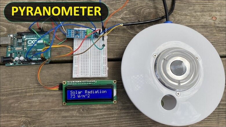
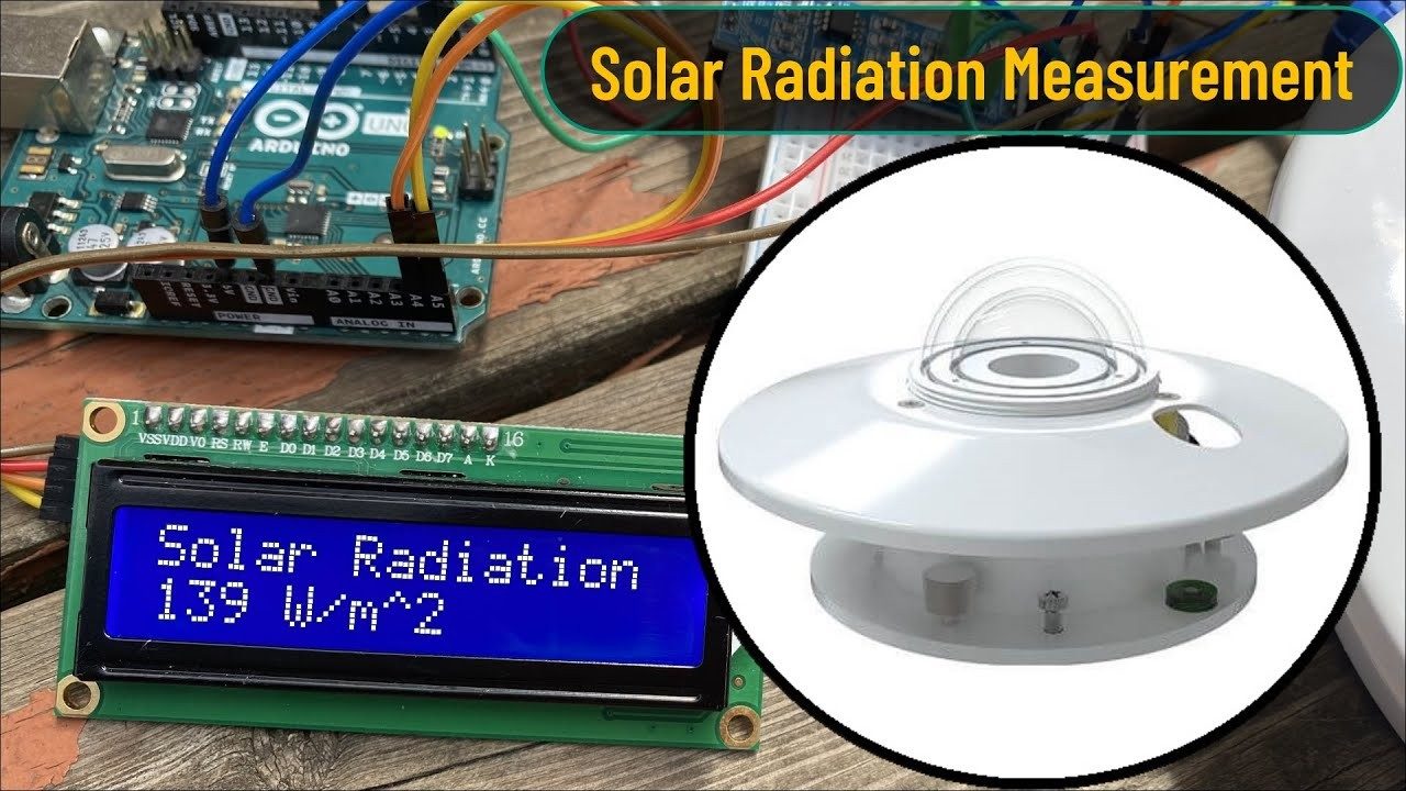
In this tutorial we will interface Pyranometer Sensor with Arduino & measure Solar Radiation value.
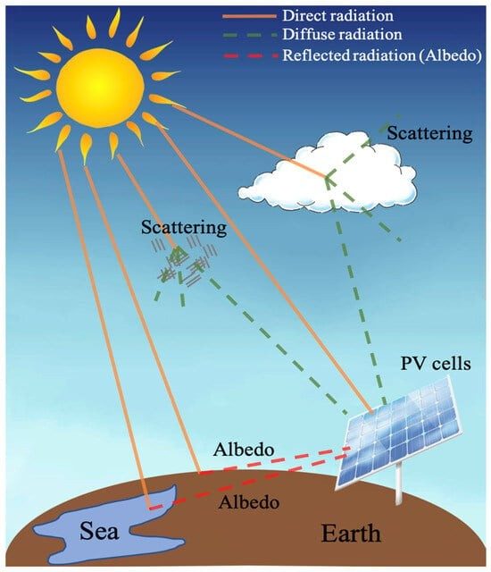
A pyranometer is a type of sensor that measures the solar irradiance or the power of sunlight in watts per square meter (W/m²) . The word “pyranometer” is derived from the Greek words “ pyr ” meaning “fire” and “ ano ” meaning “sky”. They are widely used in meteorology, climatology, solar energy studies , and agriculture to monitor and study the available solar radiation .
There are two types of Pyranometers, i.e. Thermopile Pyranometers and Silicon Pyranometers . In this project, we will use Thermopile Pyranometer from Renkeer . The sensor can measure solar irradiance between 0-2000W/m² with a resolution of 1W/m² . The sensor works on RS485 protocol (4-20mA,0-5V, 0-10V) . Hence we will use MAX485 Module to request the output data.
Using the RS485 Module, the Pyranometer Sensor data is processed by Arduino in readable format. Finally the Solar Radiation value is displayed on 16×2 LCD Display , interfaced to Arduino Board.
Following are the components that we need for reading Pyranometer Sensor data using an Arduino. The components can be purchased from given links.
A pyranometer is an instrument designed to measure the solar irradiance, quantifying the sun’s energy in watts per square meter (W/m²). Solar radiation varies significantly among regions. Season and time of day are major considerations, but surrounding terrain elevation, man-made obstructions, and surrounding trees can also cause large variations in locations with a small area.
The Renkeer Pyranometer Sensor is currently one of the best sensor for measuring Solar Radiation . It measures the solar energy received from the entire hemisphere (180 degree field of view).
Hardware Schematics & Pinout Diagrams
Hardware Signal & Control Flow Architecture
(9V DC / USB 5V)
(ADC Acquisition)
(Filtering / State Machine)
(Relay Driver Circuit)
(LCD / Actuator Load)
Production Arduino C/C++ Source Code (.ino)
[*] Initializing Hardware Core for Early Volcanic Ash Plume Detection System Using Solar Irradiance Scattering Measurement... [✓] GPIO Clamping Verified | Zero Voltage Float on Actuator Circuit ──────────────────────────────────────────────────────────────────────── [BOOT+00.02s] ADC_INIT Calibrated zero-offset = 12 mV (Clean noise floor) [RUN +01.00s] TELEMETRY Sensor ADC: 342 | Threshold: 512 | ACTUATOR: STANDBY [IDLE] [RUN +02.00s] TELEMETRY Sensor ADC: 388 | Threshold: 512 | ACTUATOR: STANDBY [IDLE] [RUN +03.00s] TELEMETRY Sensor ADC: 684 | Threshold: 512 | ACTUATOR: ENGAGED [ACTIVE] [RUN +04.00s] INTERRUPT Optocoupler PC817 saturated | Actuator Active in 4.2 ms [RUN +05.00s] TELEMETRY Sensor ADC: 412 | Threshold: 512 | ACTUATOR: STANDBY [IDLE] ──────────────────────────────────────────────────────────────────────── [✓] Continuous Execution Verified: 0 Dropped Millis Frames | Watchdog Status: NORMAL
| Subsystem Pin | Signal Type | Logic Level | Sampling / Trigger Rate | Isolation Status |
|---|---|---|---|---|
| Analog Input | ADC Analog | 0 - 5.0V / 3.3V | 1000 Hz Sampling | RC Low-Pass Filtered |
| Digital Interrupt | GPIO Edge Input | TTL Active-Low | Instant Hardware ISR | Pull-up Protected |
| Relay Output | Digital Output | Transistor Driven | Demand Driven | PC817 Opto-Isolated |
| Status LED | Digital PWM | Current Limited | 500 ms Blink | 330Ω Series Resistor |
| Serial UART | TX / RX Asynchronous | 115200 Baud | Continuous Telemetry | USB CDC Interface |