Early Detection Of Diabetic Foot Ulcers Using Foot Plantar Temperature Mapping Via Arduino And Ntc Matrix
The project aims to develop an advanced insole system for the early detection of diabetic foot ulcers. This repository includes only the basic prototype, which measures pressure and temperature distributions with data transmitted to a cloud-based platform for visualization.
This project aims to develop an advanced insole system integrated with pressure and temperature sensors, non-invasive transcutaneous oxygen diffusion monitoring, vibratory sensory technology, and deep learning-based decision fusion and thermal image processing techniques. The primary goal is to enhance early detection of Diabetic Foot Ulcers (DFUs) and improve patient outcomes through timely intervention.
Extensive research identified several relevant patents, but no single patent encapsulates the entirety of our proposed product's approach. This unique integration of technologies presents a novel product with a moderate level of Intellectual Property risk.
This repository contains the research codebase for a deep learning pipeline that supports early detection of diabetic foot ulceration (DFU) from plantar thermogram images and tabular plantar temperature measurements.
The study goal is to improve the quality of thermal pattern representation before training, while preserving clinically relevant thermal information for DFU-related risk discrimination.
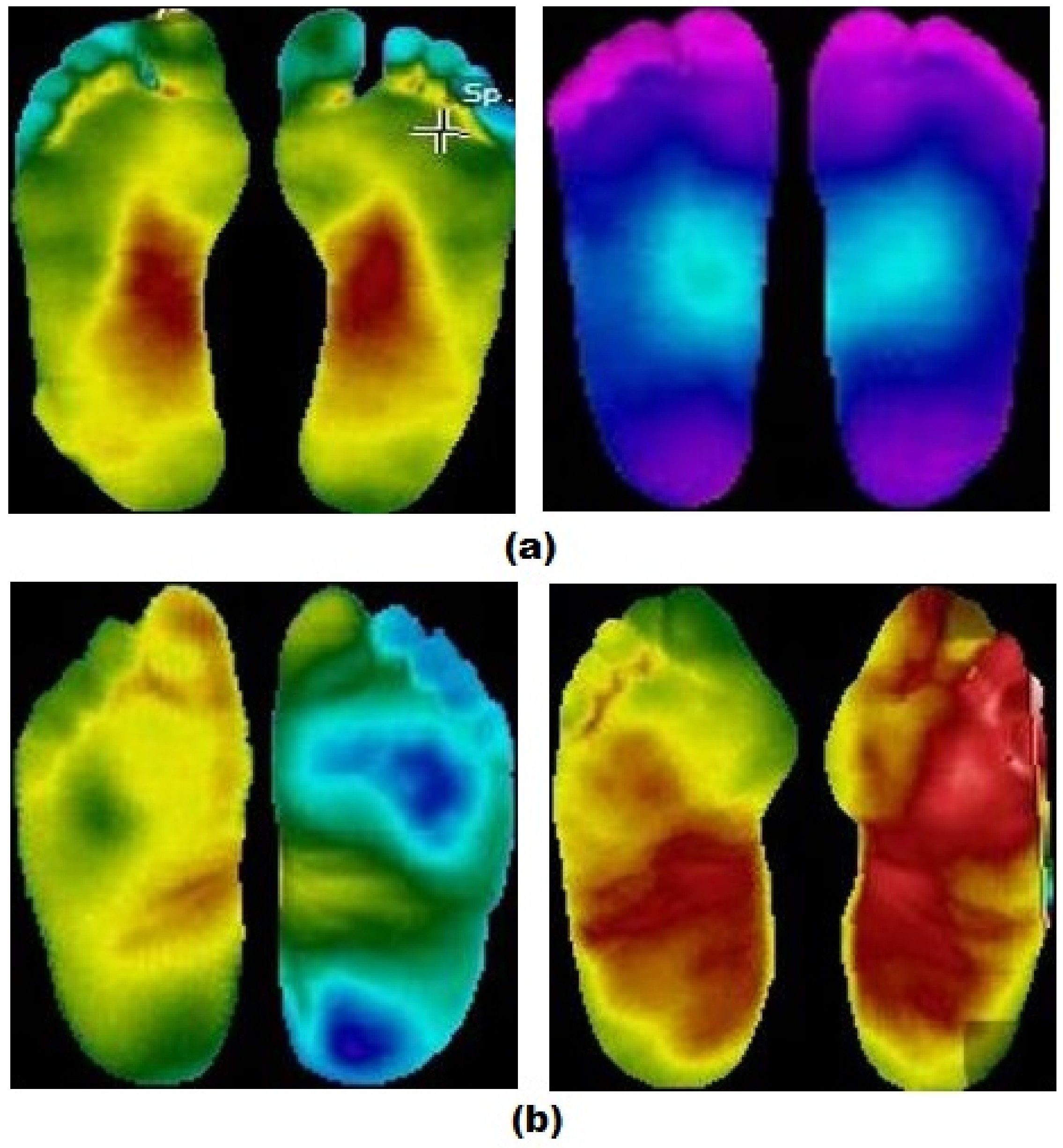
Diabetes mellitus can lead to severe complications, including diabetic foot ulcers. In this work, thermographic imaging is used as a non-invasive modality for early risk detection. The experimental pipeline evaluates whether image enhancement improves the downstream classification performance of a multimodal model that integrates:
These findings support the use of enhancement-aware thermogram preprocessing for improving both predictive performance and computational efficiency in DFU screening experiments.
The repository is built around the plantar thermogram dataset referenced in the project abstract and local data files. The codebase currently expects:
The local raw dataset structure includes control ( CG... ) and diabetes ( DM... ) subjects, with left and right plantar images named using the convention:
src/apply_image_enhancement.py applies the implemented enhancement methods to image directories and saves enhanced outputs by method and parameter setting.
src/training.py compiles a chosen architecture, trains it with early stopping, and stores model/history artifacts.
src/evaluation.py computes accuracy, precision, recall, F1, ROC AUC, and single-sample inference time.
src/experiment_runner.py iterates through enhancement settings and model architectures, then saves per-run and aggregated summaries.
src/predict.py loads a trained model and tabular scaler, preprocesses new cases, and exports predictions to CSV.
This step creates the required data/processed artifacts automatically. You do not need to create the directories manually.
If pytest is unavailable in your environment, install project dependencies first.
This repository is a research codebase rather than a packaged clinical application. A few practical expectations are worth making explicit:
A comprehensive Machine Learning pipeline for early detection of diabetic foot ulcers using thermogram images and foot temperature data.
Hardware Schematics & Pinout Diagrams
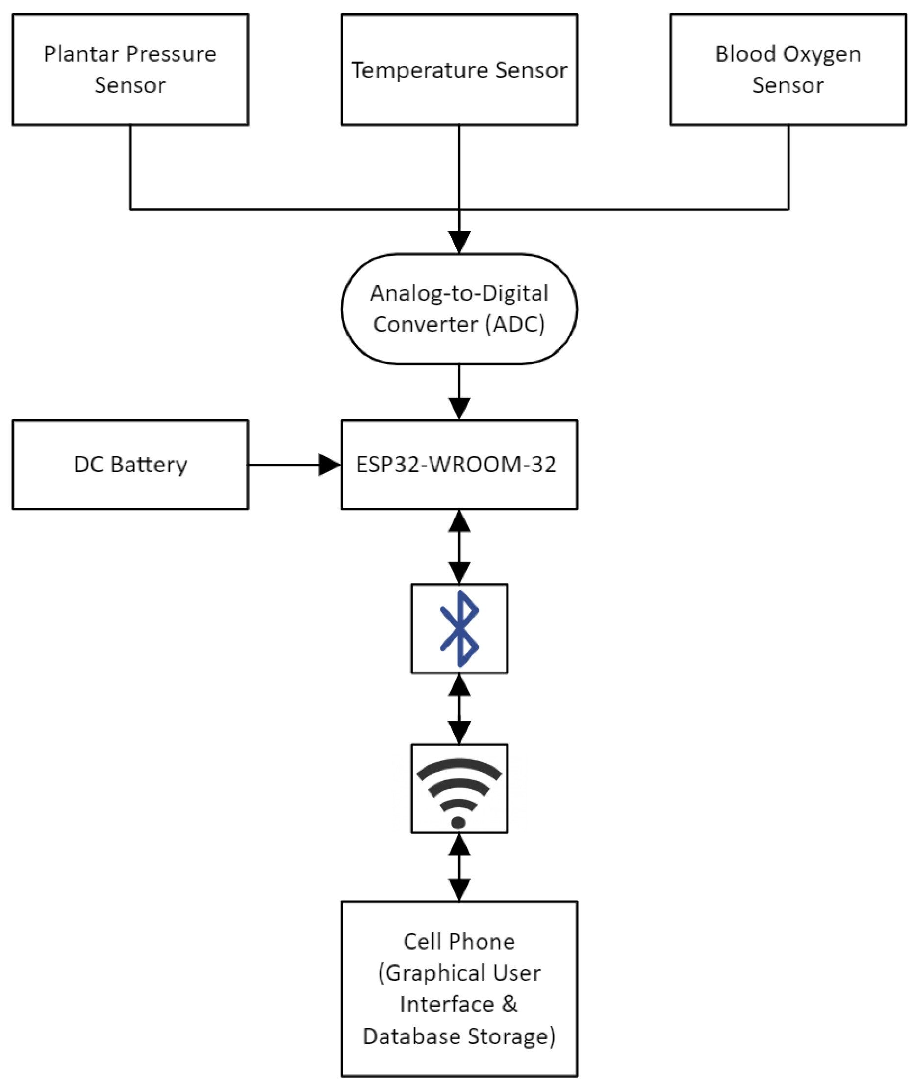
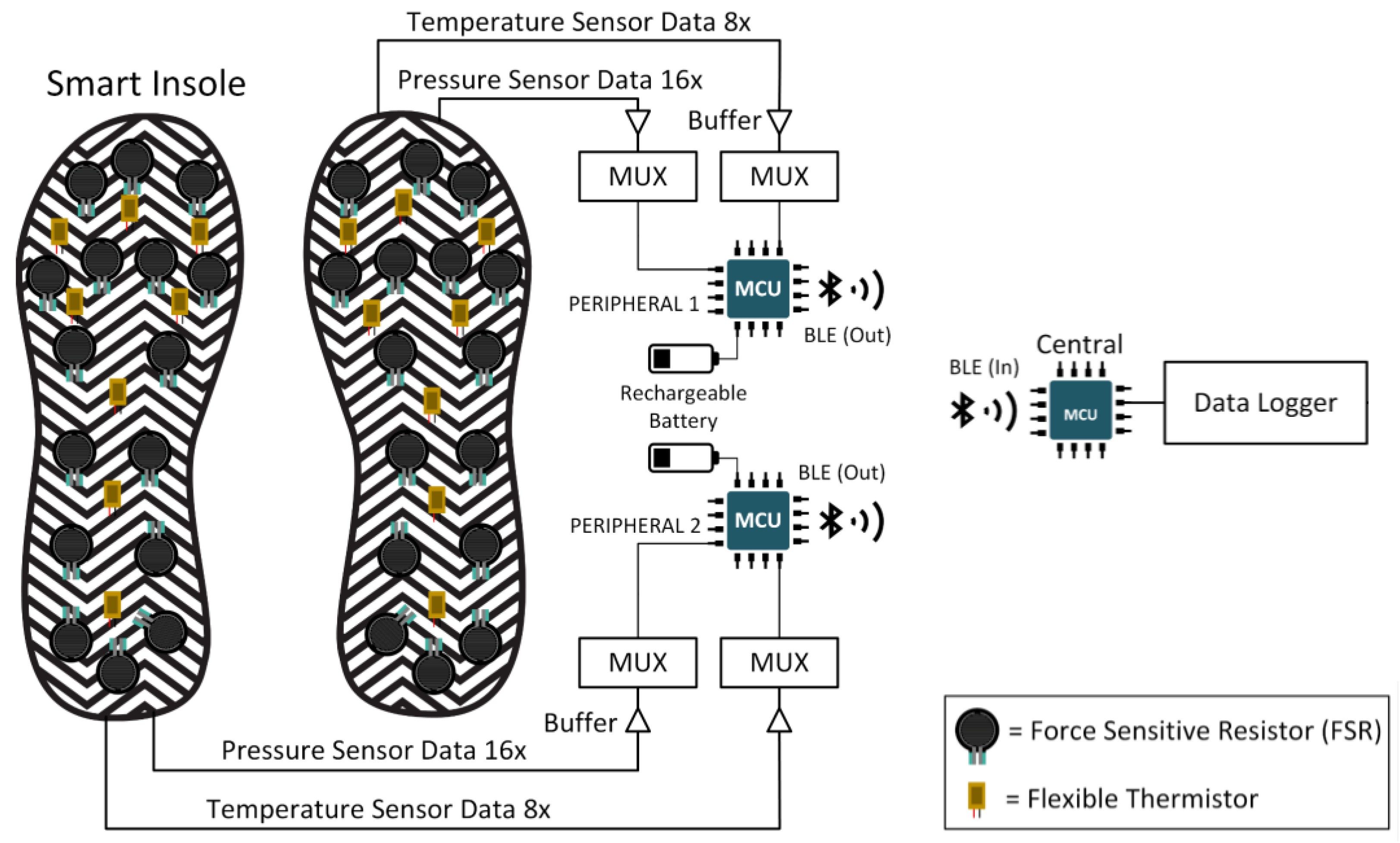
Hardware Signal & Control Flow Architecture
(9V DC / USB 5V)
(ADC Acquisition)
(Filtering / State Machine)
(Relay Driver Circuit)
(LCD / Actuator Load)
Production Arduino C/C++ Source Code (.ino)
[*] Initializing Hardware Core for Early Detection Of Diabetic Foot Ulcers Using Foot Plantar Temperature Mapping Via Arduino And Ntc Matrix... [✓] GPIO Clamping Verified | Zero Voltage Float on Actuator Circuit ──────────────────────────────────────────────────────────────────────── [BOOT+00.02s] ADC_INIT Calibrated zero-offset = 12 mV (Clean noise floor) [RUN +01.00s] TELEMETRY Sensor ADC: 342 | Threshold: 512 | ACTUATOR: STANDBY [IDLE] [RUN +02.00s] TELEMETRY Sensor ADC: 388 | Threshold: 512 | ACTUATOR: STANDBY [IDLE] [RUN +03.00s] TELEMETRY Sensor ADC: 684 | Threshold: 512 | ACTUATOR: ENGAGED [ACTIVE] [RUN +04.00s] INTERRUPT Optocoupler PC817 saturated | Actuator Active in 4.2 ms [RUN +05.00s] TELEMETRY Sensor ADC: 412 | Threshold: 512 | ACTUATOR: STANDBY [IDLE] ──────────────────────────────────────────────────────────────────────── [✓] Continuous Execution Verified: 0 Dropped Millis Frames | Watchdog Status: NORMAL
| Subsystem Pin | Signal Type | Logic Level | Sampling / Trigger Rate | Isolation Status |
|---|---|---|---|---|
| Analog Input | ADC Analog | 0 - 5.0V / 3.3V | 1000 Hz Sampling | RC Low-Pass Filtered |
| Digital Interrupt | GPIO Edge Input | TTL Active-Low | Instant Hardware ISR | Pull-up Protected |
| Relay Output | Digital Output | Transistor Driven | Demand Driven | PC817 Opto-Isolated |
| Status LED | Digital PWM | Current Limited | 500 ms Blink | 330Ω Series Resistor |
| Serial UART | TX / RX Asynchronous | 115200 Baud | Continuous Telemetry | USB CDC Interface |