Dynamic Speed Limit Warning Sign Post Triggered By Wet Road Moisture Conditions Using Arduino
Advances in embedded systems and sensors have enabled efficient, intelligent surveillance solutions that improve safety and control in transportation and automation applications. The system presented here offers a low-cost, efficient method for real-time vehicle speed monitoring using a microcontroller.
When no object or car is detected, the display shows ‘No Car Detected.’ Once an object is sensed, the system switches to speed measurement mode. Speed is calculated by measuring the time taken for a vehicle to travel between two infrared (IR) sensors placed a fixed distance apart. The timer starts when the vehicle crosses the first sensor and stops when it crosses the second.
This real-time feedback allows authorities or operators to verify whether vehicles are travelling within safe limits. If the calculated speed exceeds a preset threshold (for example, 60km/hr), the buzzer sounds to indicate overspeed. The system is therefore well-suited for areas requiring strict speed control, such as school zones, hospital campuses, and parking areas.
Fig. 1 shows the prototype assembled on a breadboard. The components required to build the system are listed in the Bill of Materials table.
Fig. 2 shows the system block diagram. It consists of two IR sensors, an Arduino board, an LCD display, and a buzzer that together perform object detection and speed monitoring. The sensors, placed at a fixed distance, detect the movement of an object as it passes between them. The Arduino serves as the main controller, receiving signals from both sensors and calculating speed from the time difference between detections.
The calculated speed and detection status are displayed on the LCD in real time. If the speed exceeds the predefined limit, the buzzer is activated to provide an audible warning, thereby enhancing road safety.
Fig. 3 shows the circuit diagram of the smart speed monitoring system. It is built around an Arduino Uno R3 board (MOD1), IR sensors (S1, S2), an LCD display (LCD1), a buzzer (B1), and supporting components. The buzzer sound indicates overspeed.
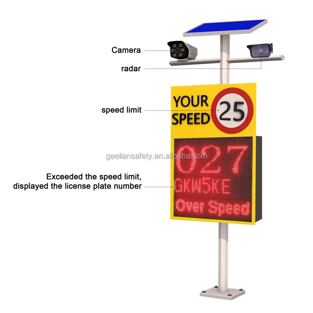
At any given moment while driving along a road, you've probably encountered one of these signs. Their large, contrasting text really stands out and grabs your attention, and the bright digits show your speed in almost any weather condition. If a car's speed is above the limit the sign will being to flash rapidly to encourage the car to slow down a bit.
These types of signs take advantage of the Doppler effect, which describes how a wave bouncing off of an approaching object will increase in frequency the closer it gets, whereas an object getting further away will decrease in frequency. By sending out a series of quick pulses in rapid succession, a very accurate speed value can be obtained and thusly displayed on the sign.
One maker, John McNelly , wanted to recreate the look and feel of the radar sign using his own custom components, which is how he came up with his Arduino Radar Speed Sign project .
McNelly's project works in much the same way as a commercially-available speed sign, with just a few small differences. He chose to use an HB100 Doppler module and pre-amplifier circuit to convert object's in its way to a square wave that the Arduino Nano can understand. The HB100 generates and transmits a 10.525GHz signal that bounces off of an object (such as a car or person) and is then picked up by a receiver.
The Doppler shift is then determined by subtracting the incoming wave's frequency from the one it sent out, therefore calculating the speed. There is a simple pre-amplifier circuit that takes the signal coming from the radar module and converts it into a square wave from a sine wave using two stages of capacitors, resistors, and op-amps.
With a way to measure speed figured out, it was time for McNelly to work on the display portion. His design uses seven distinct "segments" that each contain 18 bright, amber LEDs rather than a single one in a normal seven-segment display. Power is conveniently distributed over a pair of 12V rails that are located on the edges of each segment. To control everything, a single 74HC595 SPI shift register is used on each digit to control which segment is active and when.
Most of the circuit was placed onto a series of perf boards, including the Arduino Nano, the pair of shift registers, and the Doppler radar module. McNelly's then painstakingly soldered the 252 total LEDs (18 per segment x seven segments per digit x two digits!), along with the MOSFETs and control circuitry, to the seven-segment displays.
All of this was then assembled into a custom "Your Speed" sign that looks just like the real thing. As seen in McNelly's YouTube video below, the radar sign was able to pick up the runner's speed accurately, with him achieving a high score of 16mph. You can see the code and design files here on GitHub .
Hardware Schematics & Pinout Diagrams
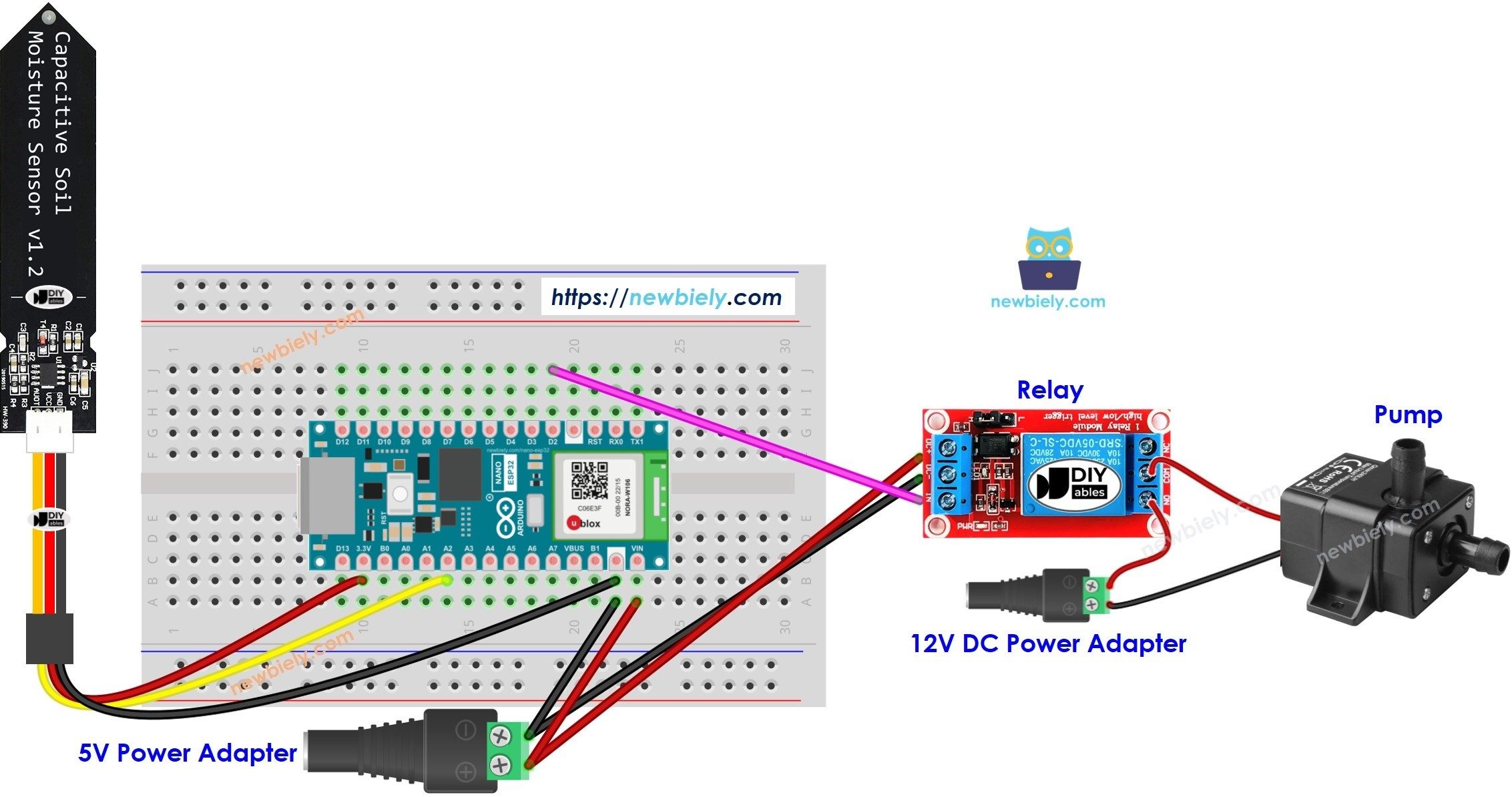
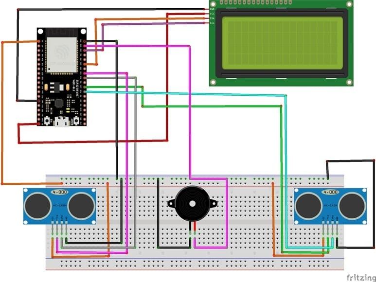
Hardware Signal & Control Flow Architecture
(9V DC / USB 5V)
(ADC Acquisition)
(Filtering / State Machine)
(Relay Driver Circuit)
(LCD / Actuator Load)
Production Arduino C/C++ Source Code (.ino)
[*] Initializing Hardware Core for Dynamic Speed Limit Warning Sign Post Triggered By Wet Road Moisture Conditions Using Arduino... [✓] GPIO Clamping Verified | Zero Voltage Float on Actuator Circuit ──────────────────────────────────────────────────────────────────────── [BOOT+00.02s] ADC_INIT Calibrated zero-offset = 12 mV (Clean noise floor) [RUN +01.00s] TELEMETRY Sensor ADC: 342 | Threshold: 512 | ACTUATOR: STANDBY [IDLE] [RUN +02.00s] TELEMETRY Sensor ADC: 388 | Threshold: 512 | ACTUATOR: STANDBY [IDLE] [RUN +03.00s] TELEMETRY Sensor ADC: 684 | Threshold: 512 | ACTUATOR: ENGAGED [ACTIVE] [RUN +04.00s] INTERRUPT Optocoupler PC817 saturated | Actuator Active in 4.2 ms [RUN +05.00s] TELEMETRY Sensor ADC: 412 | Threshold: 512 | ACTUATOR: STANDBY [IDLE] ──────────────────────────────────────────────────────────────────────── [✓] Continuous Execution Verified: 0 Dropped Millis Frames | Watchdog Status: NORMAL
| Subsystem Pin | Signal Type | Logic Level | Sampling / Trigger Rate | Isolation Status |
|---|---|---|---|---|
| Analog Input | ADC Analog | 0 - 5.0V / 3.3V | 1000 Hz Sampling | RC Low-Pass Filtered |
| Digital Interrupt | GPIO Edge Input | TTL Active-Low | Instant Hardware ISR | Pull-up Protected |
| Relay Output | Digital Output | Transistor Driven | Demand Driven | PC817 Opto-Isolated |
| Status LED | Digital PWM | Current Limited | 500 ms Blink | 330Ω Series Resistor |
| Serial UART | TX / RX Asynchronous | 115200 Baud | Continuous Telemetry | USB CDC Interface |