Drone Parachute Deployment Safety System Triggered By Free Fall Detection Via Arduino Imu
There are few versions of the code, please find the latest one in arduino_version. STM_32 mbed version is deprecated has memory overflow issues. find the cpp files in /main headers in /include.
Please do install PlatformIO extension in VSCODE or the arduino IDE, in your pc/laptop depending on which architecture and which is being used or any other if you know what you are doing .... . and do install any HC-05 bluetooth serial terminal. Like this one . Or any other as per your preference.
Connect the backup battery and main battery in any order whatsover, the system should give an error and should fire the parachute initially cause one of the battery was missing. (new feature or setup init needs to be added here). That way even the end user is assured of the system working. HIT THE RESET BUTTON Connect your device to get debug via bluetooth, as to what is happening, if everything works out good, you will get debug message on bt stating all's good, else you might find the buzzer still irritating you. And there you go The system is up and ready.
To eject the parachute, we apply the condition that it must reach a certain speed (1.5 m/s) or more within a specified time interval (0.25 s) ie an acceleration of about 6m/secsq . Otherwise, the parachute will not be ejected. Under such conditions, the drone is not allowed to reach a dangerous fall speed.
Once the parachute deploys, the system stops the spinning rotors to avoid entanglement with the parachute cords and reduces the risk of laceration injuries to people on the ground. If battery dies out relays releases spring support for the chute lid , Manual Release the flow for the chute aka stop powering the relay to hold the lid Automatic FAILSAFE MECHANISM : The above mentioned in code.
Save money with a Tuya/SmartLife energy meter monitored on Arduino Cloud via Node-RED
Today’s consumer and professional drones are very stable. They’re easy to pilot and we’re past the era of rampant out-of-control crashes. But these UAVs can still fail and benefit from a system that lets them return safely to the ground without damage. That is also true for hobby rockets, which still have very experimental controlled descent systems. To suit both types of craft, Niklas Bommersbach designed his own setup to detect critical flight behavior and then activate a two-stage parachute.
The idea is something familiar to everyone: if the aerial vehicle experiences uncontrolled descent, the parachute deploys and returns it gently to the ground for recovery. But achieving that is more difficult than you might think. Bommersbach had to engineer a robust deployment mechanism, as well as a system to trigger the deployment. He chose to load the primary parachute with a spring mechanism, plus a drogue chute as a backup. That drogue chute would also slow descent if the primary parachute fails to deploy altogether.
An Arduino Nano Every board monitors altitude using a barometric pressure sensor. It can either deploy the parachute at a set altitude when it senses rapid descent indicative of an uncontrolled fall, or it can respond to a manual command sent via radio. The chutes reside within 3D-printed containers opened servo motors. Power comes from a small lithium battery independent of the craft’s battery, so the system is self-contained. The Arduino first deploys the drogue chute, which slows descent and tries to pull out the main chute. If that fails, the Arduino can actively deploy the main chute.
This redundant and self-contained parachute system should be reliable and affordable, making it suitable for drones and experimental rockets.
An ESP8266-based parachute deployment system with a web-based control panel and NRF24L01 wireless link.
The project started as an IMU-driven autonomous deployer using an MPU6500 to detect free fall and trigger a servo. In the second phase, it evolved into a two-node wireless system where a transmitter board sends deployment commands to a receiver board over NRF24L01, allowing remote and manual control of the parachute mechanism.
This phase validated the sensor fusion and free‑fall detection pipeline and proved the mechanical deployment concept.
This architecture decouples the user interface (web, ESP8266 AP) from the physical deployment mechanism, improving reliability and range.
ESP8266‑based parachute deployment system with web UI and NRF24L01 wireless control. Initial version used an MPU‑6500 IMU for free‑fall detection; the current version adds a dedicated transmitter/receiver pair for reliable remote deployment.
Hardware Schematics & Pinout Diagrams
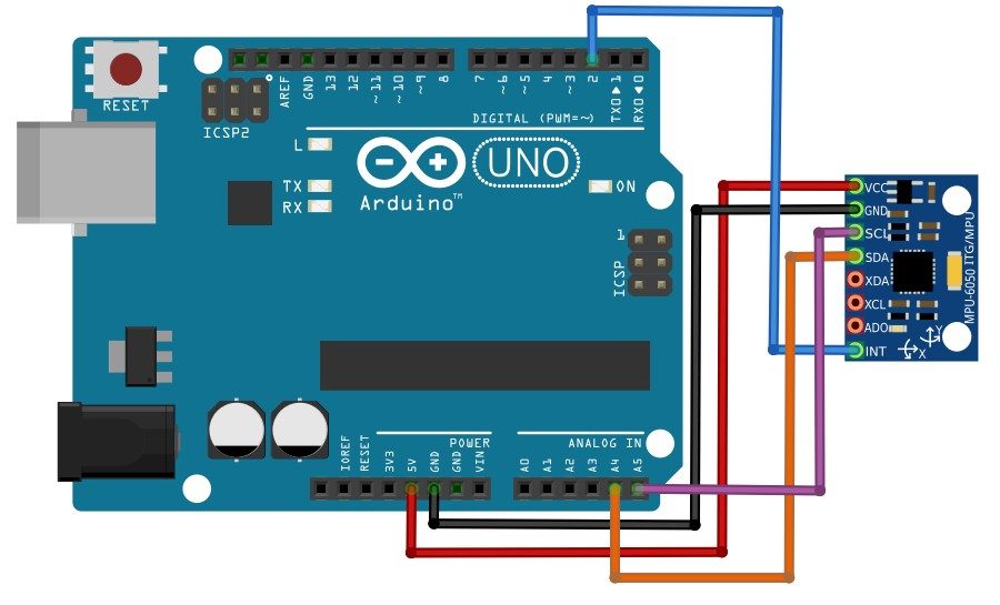
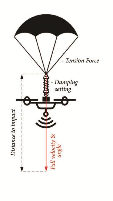
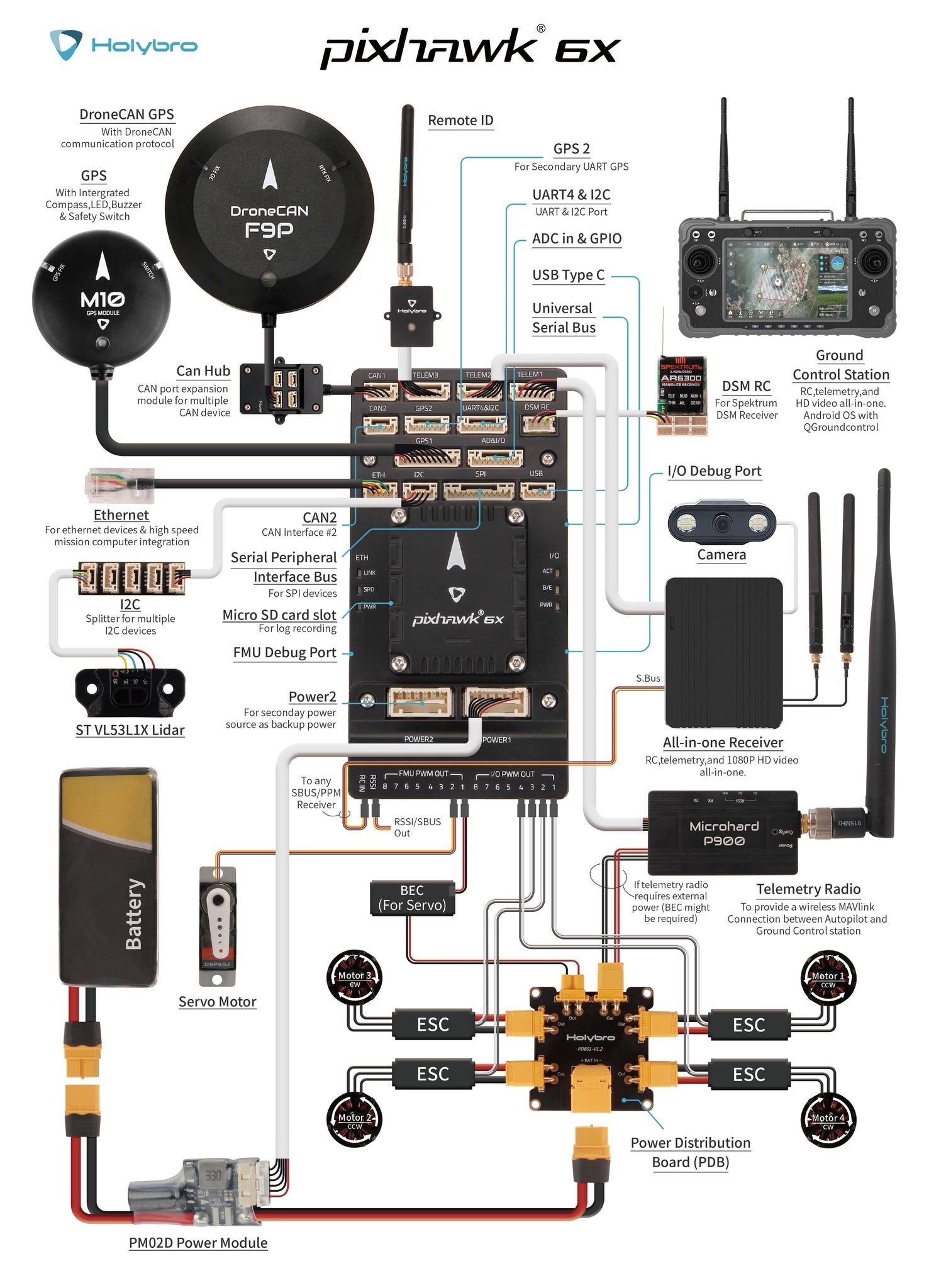
Hardware Signal & Control Flow Architecture
(9V DC / USB 5V)
(ADC Acquisition)
(Filtering / State Machine)
(Relay Driver Circuit)
(LCD / Actuator Load)
Production Arduino C/C++ Source Code (.ino)
[*] Initializing Hardware Core for Drone Parachute Deployment Safety System Triggered By Free Fall Detection Via Arduino Imu... [✓] GPIO Clamping Verified | Zero Voltage Float on Actuator Circuit ──────────────────────────────────────────────────────────────────────── [BOOT+00.02s] ADC_INIT Calibrated zero-offset = 12 mV (Clean noise floor) [RUN +01.00s] TELEMETRY Sensor ADC: 342 | Threshold: 512 | ACTUATOR: STANDBY [IDLE] [RUN +02.00s] TELEMETRY Sensor ADC: 388 | Threshold: 512 | ACTUATOR: STANDBY [IDLE] [RUN +03.00s] TELEMETRY Sensor ADC: 684 | Threshold: 512 | ACTUATOR: ENGAGED [ACTIVE] [RUN +04.00s] INTERRUPT Optocoupler PC817 saturated | Actuator Active in 4.2 ms [RUN +05.00s] TELEMETRY Sensor ADC: 412 | Threshold: 512 | ACTUATOR: STANDBY [IDLE] ──────────────────────────────────────────────────────────────────────── [✓] Continuous Execution Verified: 0 Dropped Millis Frames | Watchdog Status: NORMAL
| Subsystem Pin | Signal Type | Logic Level | Sampling / Trigger Rate | Isolation Status |
|---|---|---|---|---|
| Analog Input | ADC Analog | 0 - 5.0V / 3.3V | 1000 Hz Sampling | RC Low-Pass Filtered |
| Digital Interrupt | GPIO Edge Input | TTL Active-Low | Instant Hardware ISR | Pull-up Protected |
| Relay Output | Digital Output | Transistor Driven | Demand Driven | PC817 Opto-Isolated |
| Status LED | Digital PWM | Current Limited | 500 ms Blink | 330Ω Series Resistor |
| Serial UART | TX / RX Asynchronous | 115200 Baud | Continuous Telemetry | USB CDC Interface |