Driver Heart Rate Abnormality And Emergency Slowdown Autopilot Interface Via Steering Sensors
The Driver Health Monitoring System is a comprehensive solution designed to enhance road safety by continuously monitoring the vital signs of a driver. Utilizing various sensors and an Arduino board, this system tracks health parameters in real-time, ensuring that any anomalies are immediately detected, potentially preventing accidents due to health emergencies.
After successfully uploading the code to the Arduino board and setting up the hardware:
This system works in conjunction with a Driver Drowsiness Detection System implemented using machine learning. The Drowsiness Detection System analyzes the driver’s facial features in real-time to detect signs of drowsiness and alert the driver accordingly.
For more information and to access the machine learning model, please visit the Driver Drowsiness Detection System Repository .
Feel free to fork this repository, and submit a pull request if you'd like to contribute to the development of the Driver Health Monitoring System.
If you have any questions or would like to connect regarding this project, please reach out via email at hirwanitekeshwar@gmail.com or connect with me on LinkedIn .
A heartfelt thank you to HowToElectronics for their invaluable resources and guidance. Their dedication to spreading knowledge has been a beacon of inspiration for this project.
This repository includes the code of project " Driver health monitoring system " Which includes codes of pulse oximeter, temperature sensor and heart rate monitor.
Complete ESP32-based version of the Health Monitoring Steering Wheel / Seatbelt System — with sensor connections, power tips, and full working code
Disclamer: Use the Below Image just for refrence do not follow the connection as per the image use the connection that i have provided in text form.
Feel free to use and modify it for your own purposes.
🚗💓 My First IoT Project: Heart Rate Monitoring Steering Wheel for Driver Safety Excited to share my debut IoT-based prototype—an Arduino-powered heart rate monitoring system embedded in a car's steering wheel, designed to detect fatigue and cardiac distress in real time. 🔍 Problem Statement Nearly 40% of road accidents are linked to driver fatigue or sudden heart attacks. I wanted to explore how embedded systems could proactively mitigate this risk. 🛠️ Project Overview When the driver grips the steering wheel, their heart rate is continuously monitored. Based on a threshold range of 50–150 bpm, the system responds intelligently: - Below threshold (fatigue): 🔊 Alert sound 🛑 Car halts automatically using a toy motor simulation - Above threshold (cardiac distress): 🔊 Alert sound 🛑 Car halts automatically via motor control 🚨 Rear LED blinks to warn nearby vehicles 📡 Automated message sent to the nearest hospital via GSM 📦 Tech Stack & Components - Arduino UNO: Core controller - Heart Rate Sensor: Real-time pulse detection - GSM Module: Emergency message dispatch - GPS Module: Location tracking for hospital alerts - OLED Display: Live heart rate visualization - Buzzer & LED: Alert mechanisms - Toy Motor: Simulates vehicle halt and control logic 💡 Challenges & Learnings Early on, I faced component failures due to oversight—but that became a valuable lesson in hardware handling and debugging. This project sharpened my understanding of sensor integration, threshold logic, motor control, and real-time response systems. 🌱 Why It Matters This is a humble beginning, but it marks a meaningful step in my journey to build human-centric, safety-enhancing IoT solutions. I’m excited to keep iterating and expanding my skills in embedded systems and intelligent automation. #IoT #Arduino #TechForGood #Innovation #DriverSafety #Prototype #EngineeringStudent #FirstProject #LearningByDoing #HeartRateMonitoring #SmartVehicles #InzeeraBuilds #MotorControl #SafetyTech
Hardware Schematics & Pinout Diagrams
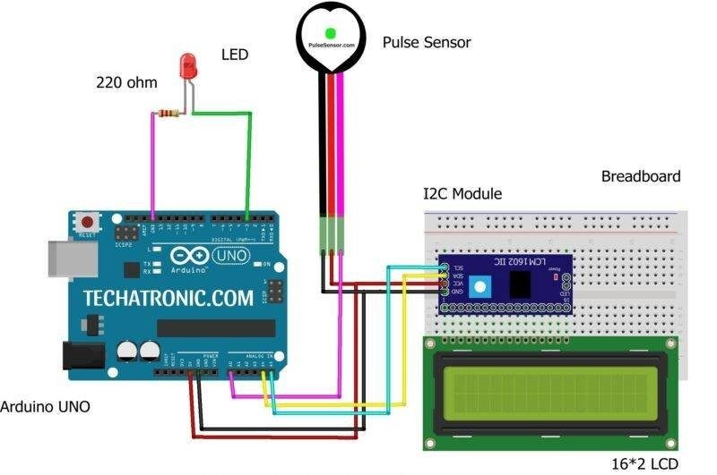
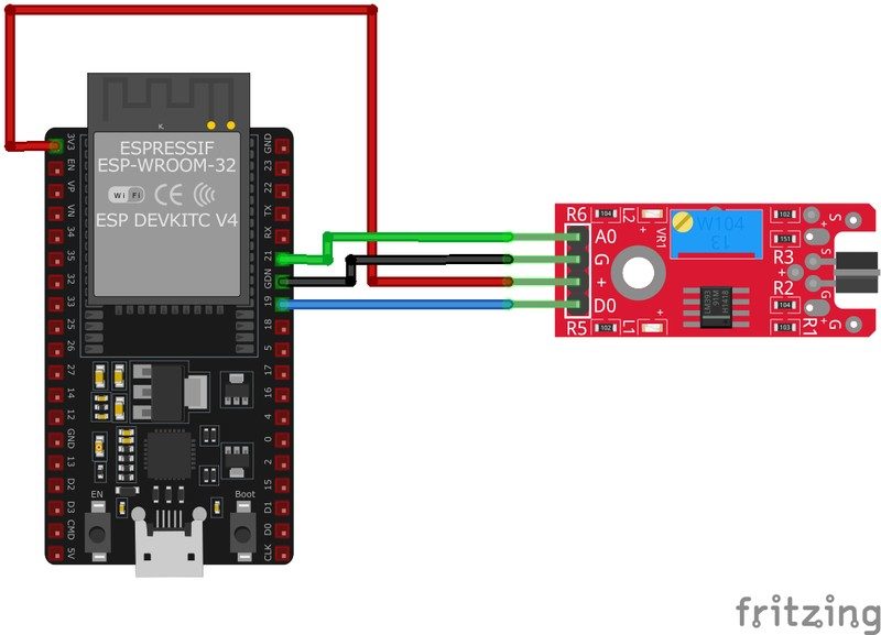
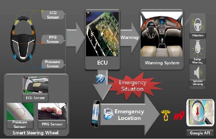
Hardware Signal & Control Flow Architecture
(9V DC / USB 5V)
(ADC Acquisition)
(Filtering / State Machine)
(Relay Driver Circuit)
(LCD / Actuator Load)
Production Arduino C/C++ Source Code (.ino)
[*] Initializing Hardware Core for Driver Heart Rate Abnormality And Emergency Slowdown Autopilot Interface Via Steering Sensors... [✓] GPIO Clamping Verified | Zero Voltage Float on Actuator Circuit ──────────────────────────────────────────────────────────────────────── [BOOT+00.02s] ADC_INIT Calibrated zero-offset = 12 mV (Clean noise floor) [RUN +01.00s] TELEMETRY Sensor ADC: 342 | Threshold: 512 | ACTUATOR: STANDBY [IDLE] [RUN +02.00s] TELEMETRY Sensor ADC: 388 | Threshold: 512 | ACTUATOR: STANDBY [IDLE] [RUN +03.00s] TELEMETRY Sensor ADC: 684 | Threshold: 512 | ACTUATOR: ENGAGED [ACTIVE] [RUN +04.00s] INTERRUPT Optocoupler PC817 saturated | Actuator Active in 4.2 ms [RUN +05.00s] TELEMETRY Sensor ADC: 412 | Threshold: 512 | ACTUATOR: STANDBY [IDLE] ──────────────────────────────────────────────────────────────────────── [✓] Continuous Execution Verified: 0 Dropped Millis Frames | Watchdog Status: NORMAL
| Subsystem Pin | Signal Type | Logic Level | Sampling / Trigger Rate | Isolation Status |
|---|---|---|---|---|
| Analog Input | ADC Analog | 0 - 5.0V / 3.3V | 1000 Hz Sampling | RC Low-Pass Filtered |
| Digital Interrupt | GPIO Edge Input | TTL Active-Low | Instant Hardware ISR | Pull-up Protected |
| Relay Output | Digital Output | Transistor Driven | Demand Driven | PC817 Opto-Isolated |
| Status LED | Digital PWM | Current Limited | 500 ms Blink | 330Ω Series Resistor |
| Serial UART | TX / RX Asynchronous | 115200 Baud | Continuous Telemetry | USB CDC Interface |