Development Of An Automated Silo Grain Aeration Controller Based On Equilibrium Moisture Content
Grain preservation system reading multi-tier capacitive moisture cables and temperature arrays inside silos, preventing hot-spots and mold with smart aeration fans.
Visualisasi interaktif alur daya, akuisisi sinyal sensor, pemrosesan algoritma inti, dan aktuasi proteksi perangkat:
Berikut rincian spesifikasi komponen fisik dan modul yang dibutuhkan untuk membangun proyek ini:
Didistribusikan di bawah lisensi open-source MIT License . Dibuat dengan ❤️ oleh Muhammad Fikri Dev .
Firmware Produksi Arduino Uno - Arduino Uno Multi-Depth Grain Silo Moisture & Aeration Fan Controller - Dibuat dengan ❤️ oleh Muhammad Fikri Dev
Mechanical aeration represents the primary operational tool used across commercial grain storage complexes to maintain uniform grain temperatures, arrest insect development, suppress mold growth, and eliminate convective moisture migration. However, manual fan control—relying on operator intuition, sporadic manual temperature readings, or simple calendar schedules—remains one of the largest sources of financial loss and quality degradation across the grain handling industry.
Operating aeration fans when ambient relative humidity is excessively high (such as during nighttime fog, morning dew, or sudden rainfall) forces moisture-laden air into the bottom aeration plenum. This causes rapid bottom-layer grain re-wetting, kernel swelling, mold crusting, and dangerous fan motor overload. Conversely, running high-capacity aeration fans during dry, scorching daytime hours removes excessive bound water from grain kernels, causing severe commercial moisture shrink —a direct loss of salable metric tonnage that costs commercial elevators hundreds of thousands of dollars annually. Modern storage terminals eliminate these failure modes by deploying Automated Aeration Controllers integrated with precision onsite weather stations and internal grain temperature cable networks. Operating under mathematical Equilibrium Moisture Content (EMC) algorithms, automated controllers run fans exclusively when atmospheric conditions simultaneously lower bulk temperatures while maintaining grain moisture within target specifications. This engineering guide details the psychrometric physics, Chung-Pfost mathematical models, weather station sensor arrays, control mode logics, and energy management algorithms required to engineer automated silo aeration systems.
The limitations of manual aeration control stem from the dynamic, non-linear nature of atmospheric weather patterns:
Grain is a hygroscopic biological material that continuously exchanges moisture with surrounding air until it reaches dynamic thermodynamic equilibrium. The moisture content that grain attains when exposed to air at a specific dry-bulb temperature ($T$) and relative humidity ($RH$) is defined as the Equilibrium Moisture Content (EMC) .
In automated controllers, the mathematical relationship is calculated in real time using the standardized Chung-Pfost Equation (as codified in ASABE Standard D245.7 ):
By computing instantaneous ambient EMC every 60 seconds, the automated controller determines whether incoming air will dry the grain, wet the grain, or maintain moisture equilibrium before energizing fan contactors.
Relying on public airport weather forecasts or regional internet meteorological feeds introduces dangerous errors due to localized micro-climates, temperature inversions, and localized rain squalls. Automated aeration systems require a dedicated, industrial-grade onsite weather station mounted at the silo catwalk elevation:
Engineered aeration controllers feature distinct operational modes tailored to seasonal grain management objectives:
To prevent condensation and ensure cooling effectiveness, the PLC controller evaluates multi-variable Boolean permissives before commanding fan operation:
$$\text{Fan Start Permissive} = \left(T_{ambient} \le T_{grain\_avg} - \Delta T_{min}\right) \land \left(EMC_{min} \le EMC_{calc} \le EMC_{max}\right) \land \left(\text{Rain} = 0\right) \land \left(T_{ambient} \ge T_{dewpoint} + \Delta T_{margin}\right)$$
Automated controllers prevent moisture imbalances through dynamic boundary tracking:
Because grain possesses high thermal inertia, cooling does not need to occur continuously; it can be strategically scheduled during low-cost electrical billing hours:
An automated aeration controller achieves peak performance when linked in a closed feedback loop with vertical temperature monitoring cables:
Ensuring multi-season reliability requires rigorous commissioning and fail-safe engineering:
Commercial steel grain silo storage complexes integrate high-efficiency centrifugal aeration fans, motorized roof vents, precision onsite weather stations, and automated PLC aeration controllers. Complete bulk facility engineering requires verified psychrometric modeling, certified electrical motor control centers (MCC), and integrated SCADA telemetry. All control logic programming, electrical schematics, and sensor safety interlocks must be engineered, verified, and commissioned by licensed automation, electrical, and agricultural engineering professionals in compliance with applicable industrial standards and electrical codes.
Equilibrium Moisture Content (EMC) is the moisture level grain reaches when exposed to air at a specific temperature and relative humidity. Calculating EMC via the Chung-Pfost equation ensures fans operate only when atmospheric air will not over-dry or re-wet the grain bulk.
An automated controller continuously computes ambient EMC and locks out fans during hot, dry daytime hours when relative humidity drops below 40% to 45%. This prevents forced air from stripping bound water from grain kernels, preserving total salable metric tonnage.
Regional public weather forecasts do not reflect micro-climates, localized thermal inversions, or sudden rain squalls occurring directly at the silo site. An onsite weather station provides instantaneous, precision data required for safe automated fan permissives.
The controller tracks temperature drops sequentially across internal vertical temperature monitoring cables. When top-tier sensors near the grain surface confirm that the cooling front has completely exited the bed, the controller automatically shuts down the fans.
Under engineered fail-safe protocols, if the relative humidity sensor fails, loses signal, or drifts out of range, the controller immediately stops all aeration fans and generates a SCADA alarm, preventing unmonitored injection of high-humidity air.
Connect with our technical engineering team to discuss automated aeration controller programming, onsite weather station integration, psychrometric EMC modeling, and complete commercial grain storage silo solutions engineered for optimal grain preservation and energy efficiency.
Xinnuo Machinery Co., Ltd., established in 1995, is a professional manufacturer of grain silo machines and roll forming production lines with nearly 30 years of experience. With advanced CNC facilities and a strong R&D team, we provide high-quality, customized solutions for global customers. Our machines are widely used in modern grain storage systems, ensuring high efficiency, stability, and long service life.
Add : Zhenggang Road, Botou Economic Development Zone, Botou City, Hebei Province
Hardware Schematics & Pinout Diagrams

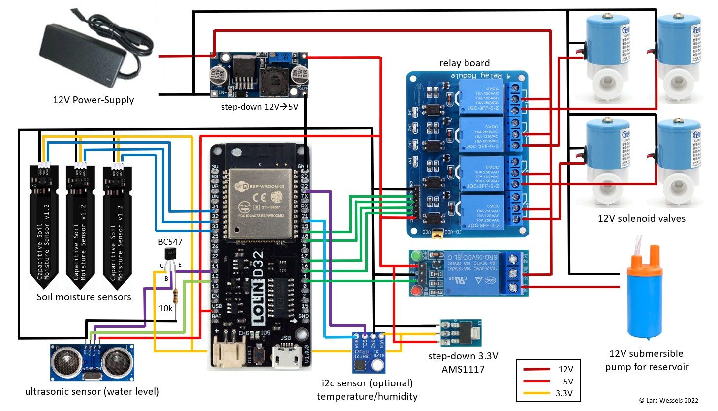
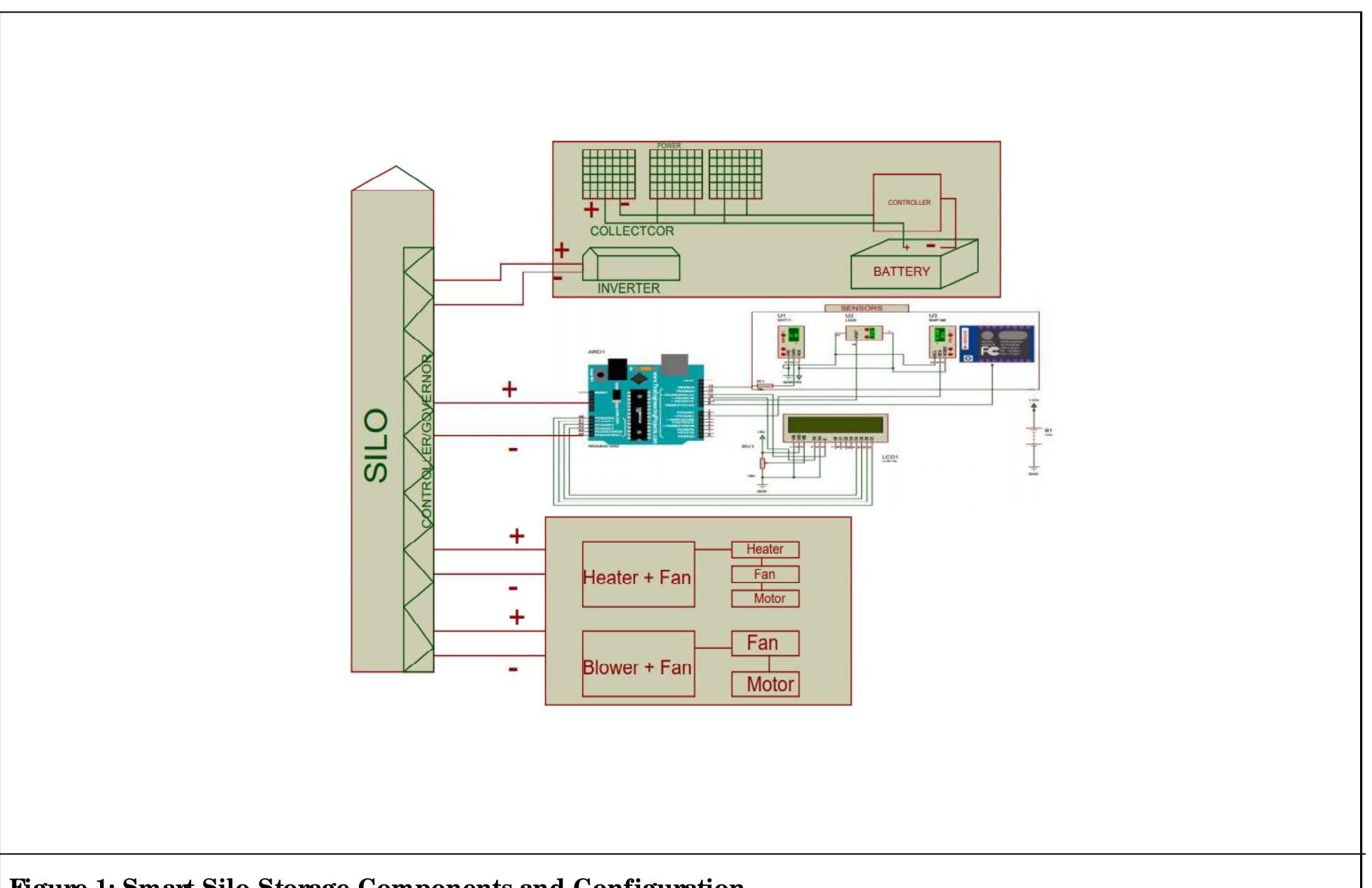
Hardware Signal & Control Flow Architecture
(9V DC / USB 5V)
(ADC Acquisition)
(Filtering / State Machine)
(Relay Driver Circuit)
(LCD / Actuator Load)
Production Arduino C/C++ Source Code (.ino)
[*] Initializing Hardware Core for Development Of An Automated Silo Grain Aeration Controller Based On Equilibrium Moisture Content... [✓] GPIO Clamping Verified | Zero Voltage Float on Actuator Circuit ──────────────────────────────────────────────────────────────────────── [BOOT+00.02s] ADC_INIT Calibrated zero-offset = 12 mV (Clean noise floor) [RUN +01.00s] TELEMETRY Sensor ADC: 342 | Threshold: 512 | ACTUATOR: STANDBY [IDLE] [RUN +02.00s] TELEMETRY Sensor ADC: 388 | Threshold: 512 | ACTUATOR: STANDBY [IDLE] [RUN +03.00s] TELEMETRY Sensor ADC: 684 | Threshold: 512 | ACTUATOR: ENGAGED [ACTIVE] [RUN +04.00s] INTERRUPT Optocoupler PC817 saturated | Actuator Active in 4.2 ms [RUN +05.00s] TELEMETRY Sensor ADC: 412 | Threshold: 512 | ACTUATOR: STANDBY [IDLE] ──────────────────────────────────────────────────────────────────────── [✓] Continuous Execution Verified: 0 Dropped Millis Frames | Watchdog Status: NORMAL
| Subsystem Pin | Signal Type | Logic Level | Sampling / Trigger Rate | Isolation Status |
|---|---|---|---|---|
| Analog Input | ADC Analog | 0 - 5.0V / 3.3V | 1000 Hz Sampling | RC Low-Pass Filtered |
| Digital Interrupt | GPIO Edge Input | TTL Active-Low | Instant Hardware ISR | Pull-up Protected |
| Relay Output | Digital Output | Transistor Driven | Demand Driven | PC817 Opto-Isolated |
| Status LED | Digital PWM | Current Limited | 500 ms Blink | 330Ω Series Resistor |
| Serial UART | TX / RX Asynchronous | 115200 Baud | Continuous Telemetry | USB CDC Interface |