Development Of An Arduino Based Diagnostic Spirometer With Real Time Pulmonary Function Telemetry
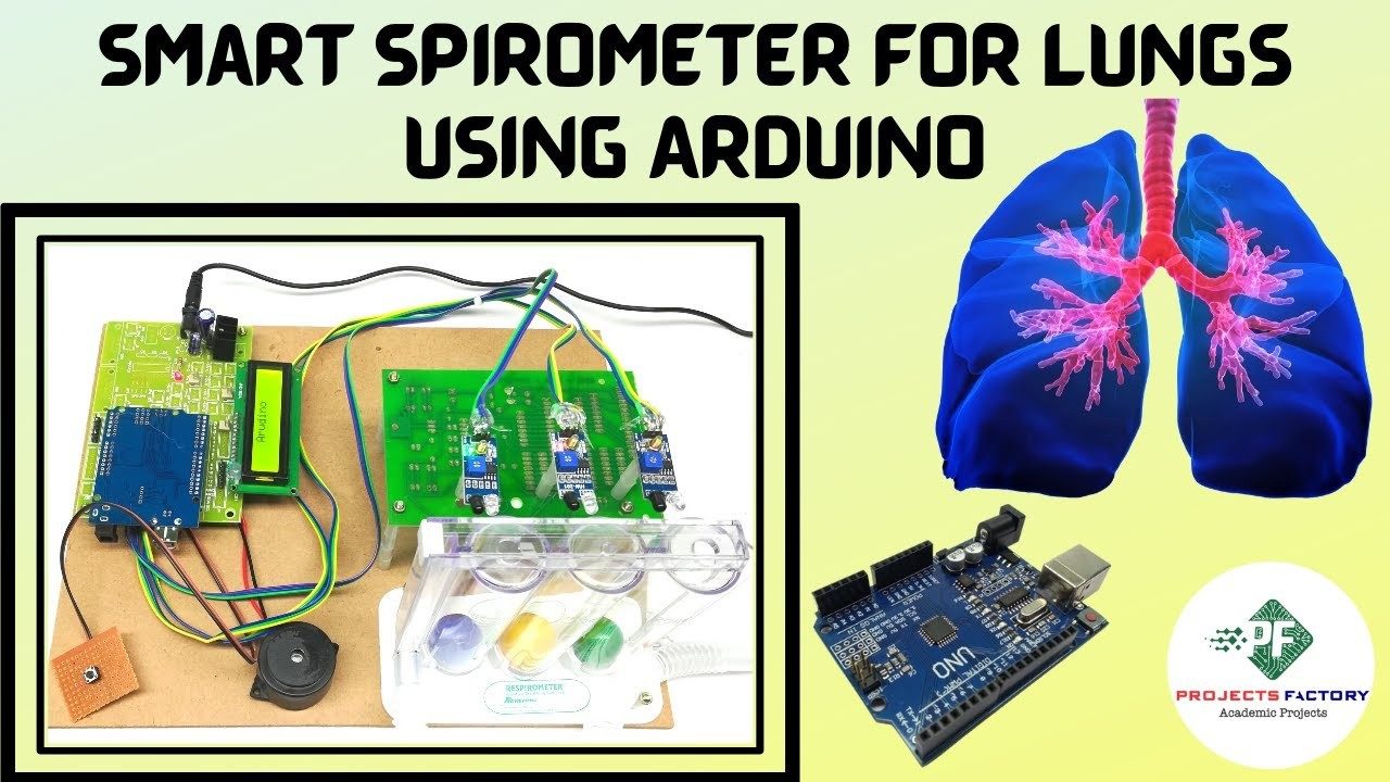
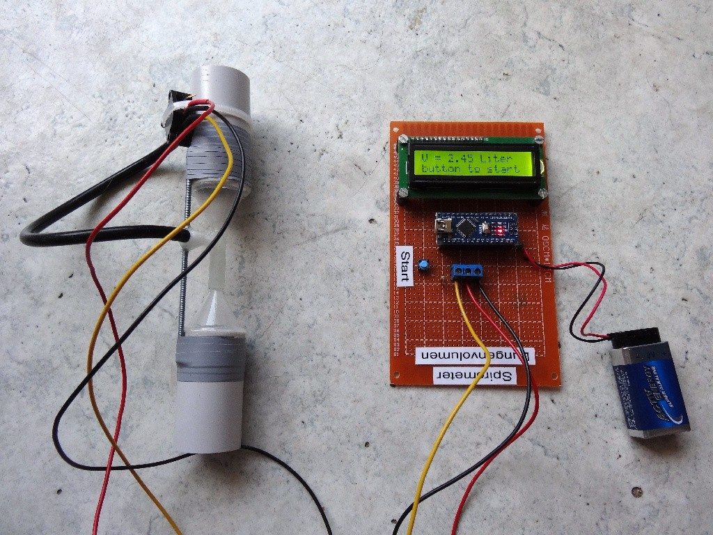
A portable, Arduino-based digital spirometer for measuring respiratory volumes and lung capacity. This device provides real-time breath analysis with an intuitive OLED interface, enabling clinical respiratory assessments through multi-mode measurement capabilities including forced vital capacity (FVC) analysis.
Traditional spirometers are expensive and often inaccessible in low-resource settings. This project democratizes respiratory health monitoring by providing an open-source, cost-effective alternative using readily available Arduino components. It enables accurate measurement of lung capacity metrics essential for diagnosing respiratory conditions, monitoring asthma, and tracking post-operative recovery.
Arduino-based digital spirometer for measuring respiratory volumes and lung capacity.
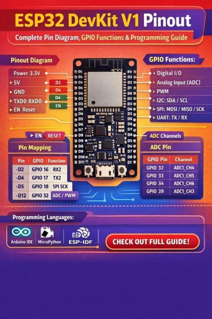
SpiroX is a smart digital spirometer designed to assess lung function by measuring airflow pressure during inhalation and exhalation. It uses a HX710B ADC Module + MPS20N0040D pressure sensor, ESP8266(WeMos D1 Mini), SSD1306 OLED display, and LED bar(SHB10W) to provide real-time breathing performance visualisation.
SpiroX is a smart digital spirometer developed to assess lung function by measuring air pressure generated during breathing. The system uses an MPS20N0040D pressure sensor with an HX710B ADC module to capture breathing pressure accurately. This provides an affordable and portable solution for respiratory monitoring.
The measured pressure data is processed by a WeMos ESP8266 microcontroller. Real-time results are displayed on an OLED screen, while a 10-level LED bar visually indicates breathing strength from weak to strong. This allows users to instantly understand their lung performance during testing.
SpiroX helps in monitoring respiratory conditions such as asthma and reduced lung capacity. It can be used in healthcare, home monitoring, medical education, and clinical assessment. The device is compact, low-cost, and easy to operate compared to traditional spirometers.
In addition to hardware monitoring, SpiroX includes a web dashboard that stores the history of previous lung tests for long-term analysis. Jury can access the dashboard using the provided website link and demo login credentials to review stored records and performance tracking.
The MPS20N0040D pressure sensor detects the air pressure when a patient blows into the tube. Since its output signal is very small, it must be amplified and converted into digital data using the HX710B.
The first shift register controls LEDs 1–8 of the LED bar graph.This shift register receives data from the ESP8266.
Use a 220Ω resistor in series with every LED. First 74HC595 O/P LED Q0 LED1 Q1 LED2 Q2 LED3 Q3 LED4 Q4 LED5 Q5 LED6 Q6 LED7 Q7 LED8
Pressure values are mapped into 10 levels: Level 0–3 → Keep Practicing₹ Level 4–6 → keep Going Level 7–9 → Good Level 10 → Excellent
SPIROX successfully demonstrates a smart and affordable spirometer for lung function assessment using pressure sensing technology. By combining the MPS20N0040D pressure sensor , HX710B ADC , and WeMos ESP8266 , the system accurately measures breathing pressure and converts it into meaningful lung performance data.
The device provides real-time feedback through an OLED display and 10-level LED bar , allowing users to instantly visualize their breathing strength from weak to excellent. Its compact design, low cost, and ease of use make it suitable for healthcare monitoring, educational purposes, and clinical assessment.
In addition to hardware-based monitoring, SPIROX also includes a web dashboard for storing previous test records. The website maintains historical data and presents it using graphical representations such as charts and performance trends , enabling users and healthcare professionals to easily analyze progress, compare past results, and track long-term respiratory health.
COVID-19 , respiratory diseases , spirometry test , oxygen levels , spirometer , Forced vital capacity (FVC) , check restricted breathing .
Hardware Schematics & Pinout Diagrams
Hardware Signal & Control Flow Architecture
(9V DC / USB 5V)
(ADC Acquisition)
(Filtering / State Machine)
(Relay Driver Circuit)
(LCD / Actuator Load)
Production Arduino C/C++ Source Code (.ino)
[*] Initializing Hardware Core for Development Of An Arduino Based Diagnostic Spirometer With Real Time Pulmonary Function Telemetry... [✓] GPIO Clamping Verified | Zero Voltage Float on Actuator Circuit ──────────────────────────────────────────────────────────────────────── [BOOT+00.02s] ADC_INIT Calibrated zero-offset = 12 mV (Clean noise floor) [RUN +01.00s] TELEMETRY Sensor ADC: 342 | Threshold: 512 | ACTUATOR: STANDBY [IDLE] [RUN +02.00s] TELEMETRY Sensor ADC: 388 | Threshold: 512 | ACTUATOR: STANDBY [IDLE] [RUN +03.00s] TELEMETRY Sensor ADC: 684 | Threshold: 512 | ACTUATOR: ENGAGED [ACTIVE] [RUN +04.00s] INTERRUPT Optocoupler PC817 saturated | Actuator Active in 4.2 ms [RUN +05.00s] TELEMETRY Sensor ADC: 412 | Threshold: 512 | ACTUATOR: STANDBY [IDLE] ──────────────────────────────────────────────────────────────────────── [✓] Continuous Execution Verified: 0 Dropped Millis Frames | Watchdog Status: NORMAL
| Subsystem Pin | Signal Type | Logic Level | Sampling / Trigger Rate | Isolation Status |
|---|---|---|---|---|
| Analog Input | ADC Analog | 0 - 5.0V / 3.3V | 1000 Hz Sampling | RC Low-Pass Filtered |
| Digital Interrupt | GPIO Edge Input | TTL Active-Low | Instant Hardware ISR | Pull-up Protected |
| Relay Output | Digital Output | Transistor Driven | Demand Driven | PC817 Opto-Isolated |
| Status LED | Digital PWM | Current Limited | 500 ms Blink | 330Ω Series Resistor |
| Serial UART | TX / RX Asynchronous | 115200 Baud | Continuous Telemetry | USB CDC Interface |