Development Of A Wearable Heat Stroke Warning System For Outdoor Workers Using Arduino And Core Temp Estimation
HeatShield is a smart temperature monitoring system developed using Arduino Uno and a TMP36 temperature sensor to help prevent heat stroke among industrial workers.
Smart Temperature Monitoring System for Heat Stroke Prevention in Industrial Workers using Arduino and TMP36 Sensor.
Automatic body cooling Arduino-controlled cooling system Real-time temperature monitoring Peltier thermoelectric cooling PCM cooling packs High-speed cooling fans USB-C rechargeable battery Lightweight wearable design Long battery backup Low power consumption Portable and comfortable Adjustable cooling levels Smart thermal management Worker safety enhancement Easy maintenance
Perfect for your college submission with complete documentation and source code. Get this project now and save valuable development time!
🛡️ Trust Factor: Every project report is guaranteed plagiarism-free and verified human-written. You can check your own reports using our in-house Free AI Content Detector .
The Automatic Plant Watering System using Arduino UNO is an intelligent irrigation system ...
The Pick and Place Robotic Arm using Arduino is an intelligent robotic automation system d...
The Fruit Plucking Robot using Arduino is an intelligent agricultural automation system de...
The device uses two Bluetooth-linked Fire Beetle BTE 4.1 boards paired with Arduino to collect sensor data and relay real-time information to a custom user interface.
The UI displays live sensor data, including heart rate graphs, temperature and humidity readings, UV index monitoring, and activity intensity visualization.
Heat stroke is a dangerous and sometimes fatal condition caused by prolonged exposure to high temperatures. In the U.S. alone, it contributes to over 700 deaths annually. High UV exposure and humidity increase risks—especially for vulnerable populations such as the elderly.
Wearable technologies offer a modern solution by enabling real-time environmental and physiological monitoring. This project introduces a wristband capable of tracking heart rate, UV exposure, temperature, and humidity to provide early warnings of dangerous heat conditions.
By integrating multiple sensors with a responsive UI, this project demonstrates how wearable technology can enhance personal health safety, particularly in increasingly uncertain environmental conditions.
The heart rate monitor and UV sensor communicate via I²C, requiring connections to SDA/SCL pins on the Fire Beetle board.
This organization ensures smooth data collection and efficient sensor performance.
The team used Figma to prototype the user interface before implementation. Figma offered:
The prototype served as a blueprint for the final UI, ensuring feature alignment and helping predict design and development issues early.
The UI aims to provide a seamless, responsive, and intuitive real-time monitoring experience.
Course : Wearables and Nearables Semester : Fall 2024 Institution : University of Illinois Chicago (UIC)
Wearable health technology can play a critical role in preventing heat-related illnesses. By integrating multiple sensors, Bluetooth communication, and a responsive user interface, the wristband provides real-time data for personal safety.
The project highlights the importance of sensor accuracy, intuitive UX design, and reliable signal processing, laying the foundation for future enhancements such as advanced analytics, mobile integration, and broader applications in environmental health monitoring.
A wearable heat-stroke prevention wristband.
Hardware Schematics & Pinout Diagrams
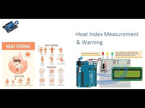
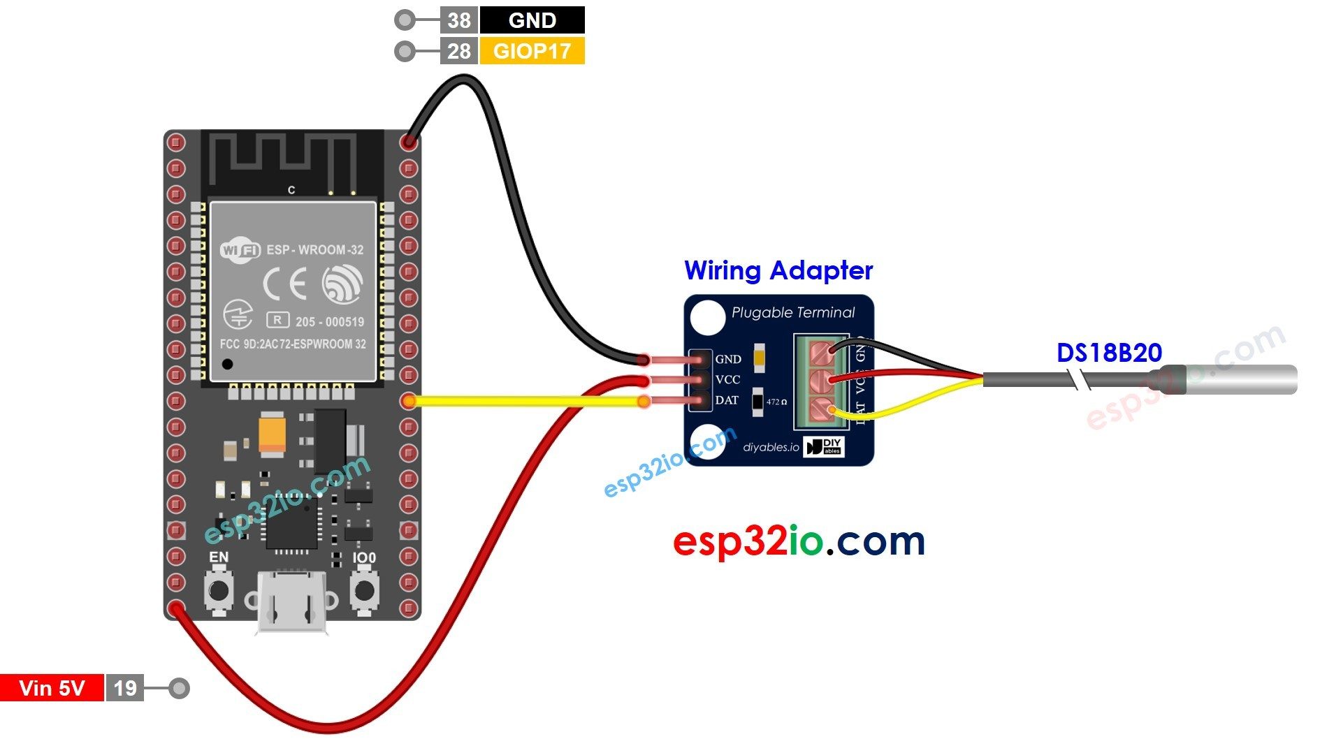

Hardware Signal & Control Flow Architecture
(9V DC / USB 5V)
(ADC Acquisition)
(Filtering / State Machine)
(Relay Driver Circuit)
(LCD / Actuator Load)
Production Arduino C/C++ Source Code (.ino)
[*] Initializing Hardware Core for Development Of A Wearable Heat Stroke Warning System For Outdoor Workers Using Arduino And Core Temp Estimation... [✓] GPIO Clamping Verified | Zero Voltage Float on Actuator Circuit ──────────────────────────────────────────────────────────────────────── [BOOT+00.02s] ADC_INIT Calibrated zero-offset = 12 mV (Clean noise floor) [RUN +01.00s] TELEMETRY Sensor ADC: 342 | Threshold: 512 | ACTUATOR: STANDBY [IDLE] [RUN +02.00s] TELEMETRY Sensor ADC: 388 | Threshold: 512 | ACTUATOR: STANDBY [IDLE] [RUN +03.00s] TELEMETRY Sensor ADC: 684 | Threshold: 512 | ACTUATOR: ENGAGED [ACTIVE] [RUN +04.00s] INTERRUPT Optocoupler PC817 saturated | Actuator Active in 4.2 ms [RUN +05.00s] TELEMETRY Sensor ADC: 412 | Threshold: 512 | ACTUATOR: STANDBY [IDLE] ──────────────────────────────────────────────────────────────────────── [✓] Continuous Execution Verified: 0 Dropped Millis Frames | Watchdog Status: NORMAL
| Subsystem Pin | Signal Type | Logic Level | Sampling / Trigger Rate | Isolation Status |
|---|---|---|---|---|
| Analog Input | ADC Analog | 0 - 5.0V / 3.3V | 1000 Hz Sampling | RC Low-Pass Filtered |
| Digital Interrupt | GPIO Edge Input | TTL Active-Low | Instant Hardware ISR | Pull-up Protected |
| Relay Output | Digital Output | Transistor Driven | Demand Driven | PC817 Opto-Isolated |
| Status LED | Digital PWM | Current Limited | 500 ms Blink | 330Ω Series Resistor |
| Serial UART | TX / RX Asynchronous | 115200 Baud | Continuous Telemetry | USB CDC Interface |