Development Of A Pipeline Inspection Robot With Active Radial Expansion And Live Video Link
Nowadays, pipelines are essential for transporting fluids and gases, but they need regular checks to work properly. However, it's risky for humans to inspect them, especially in tight or dangerous spots. This research focuses on creating a low-cost robot to inspect pipelines for cracks and blockages using cameras. The 3D Modelling of the robot was designed using Autodesk Fusion 360, and it was controlled with ARDUINO UNO and L298N-H-Bridge controllers. It takes internal pictures using esp32 and detects obstacles with ultrasonic sensors. Techniques for finding cracks and holes were also developed. The system was tested using real photos from esp32. Additionally, the system can record and display the view of the atmosphere on the employee’s monitor display screen for effective observation, detection, quick analysis, diagnosis and reliably in confined, dark environments.
Arduino Uno: This is the main microcontroller board, featuring an Atmega328P chip. It's widely used due to its simplicity and versatility in handling various tasks.
Arduino Nano: Similar to the Uno but in a smaller form factor, the Nano is often used in projects where space is limited or where a more compact design is desired. It offers similar functionality to the Uno.
HC-12 Module: The HC-12 is a wireless transceiver module that operates on the 433 MHz frequency. It enables communication between devices over long distances, making it ideal for remote control or data transmission in projects like remote sensing or telemetry systems.
ESP32 Cam: Camera Module: The ESP32-CAM is a compact development board that combines an ESP32 microcontroller with a camera module. It allows for capturing images and video, making it suitable for projects involving surveillance, monitoring, or image processing.
L298N Speed Controller: The L298N is a motor driver module capable of controlling the speed and direction of DC motors. It's commonly used in robotics projects for driving wheels or other moving parts, providing efficient motor control.
Motors (1000 Rpm): These are DC motors with a speed of 1000 RPM (Rotations Per Minute). They provide the mechanical movement necessary for the project, such as driving wheels or other locomotion mechanisms in a robot.
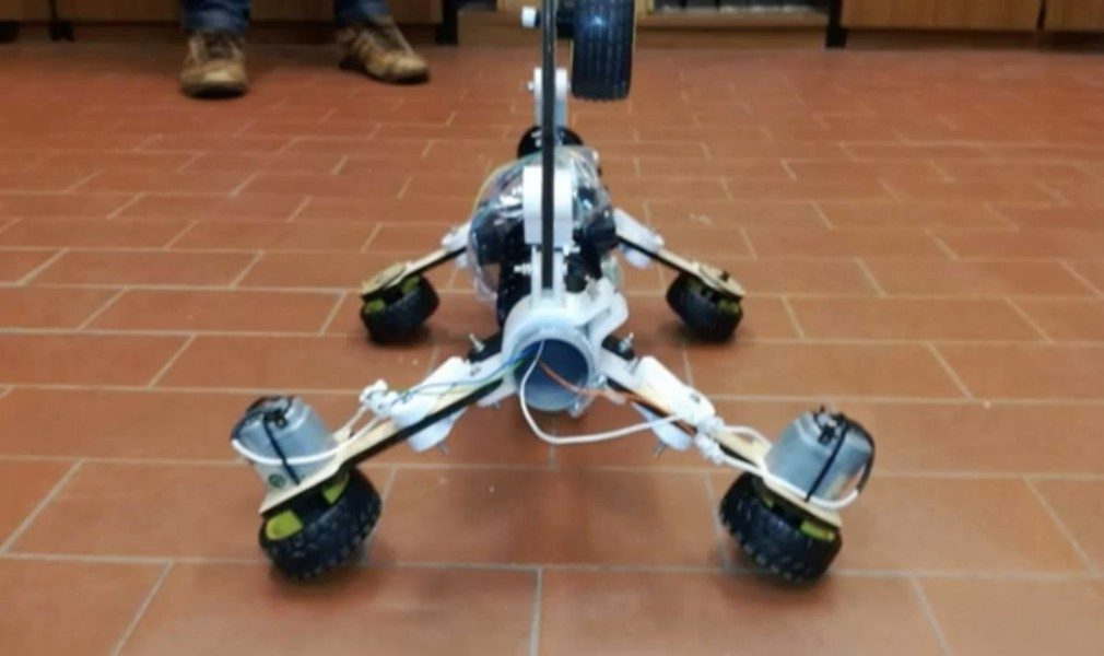
The field of robotics has seen significant advancements, especially in industries like manufacturing, where robots are deployed for various tasks, such as welding and painting, improving safety and efficiency. Pipelines serve as vital infrastructure for fluid transportation, requiring regular inspection to detect cracks and blockages. However, inspecting pipelines can be challenging, especially in remote or inaccessible areas. To address this challenge, a joystick-controlled pipeline inspection robot equipped with an HC-12 module has been developed. Unlike autonomous systems, this robot relies on human control via a joystick and focuses solely on detecting cracks and blockages within the pipeline. Moreover, the compact and agile nature of the robot enables it to navigate through tight spaces and intricate pipeline networks with ease. This versatility allows for comprehensive inspection coverage, even in challenging environments where access may be limited or obstructed. The joystick-controlled pipeline inspection robot offers a cost-effective and efficient solution for pipeline inspection. By utilizing a joystick interface, operators can precisely maneuver the robot through the pipeline, allowing for targeted inspection of potential problem areas. The inclusion of the HC-12 module enables wireless communication between the robot and the control station, providing real-time feedback to the operator with a range of 1000 meters. Traditional methods of pipeline inspection often involve manual inspection or costly equipment. However, these methods can be time-consuming and pose safety risks to workers. In contrast, our joystick-controlled robot eliminates the need for human entry into hazardous environments, enhancing safety and reducing operational costs. Furthermore, the primary focus of this robot is on detecting cracks and blockages within the pipeline. By employing sensors and imaging systems, the robot can accurately identify potential issues, allowing for prompt maintenance and preventing potential leaks or accidents.
In summary, the joystick-controlled pipeline inspection robot offers a versatile and efficient solution for pipeline maintenance. By combining human control with advanced technology, such as the HC-12 module, this robot streamlines the inspection process, ensuring the integrity and safety of the pipeline infrastructure. Overall, the joystick-controlled pipeline inspection robot represents a significant advancement in pipeline maintenance technology. Its combination of human control, wireless communication capabilities, and focus on crack and blockage detection make it a valuable asset for ensuring the reliability and safety of critical pipeline infrastructure.
Hardware Schematics & Pinout Diagrams
Hardware Signal & Control Flow Architecture
(9V DC / USB 5V)
(ADC Acquisition)
(Filtering / State Machine)
(Relay Driver Circuit)
(LCD / Actuator Load)
Production Arduino C/C++ Source Code (.ino)
[*] Initializing Hardware Core for Development Of A Pipeline Inspection Robot With Active Radial Expansion And Live Video Link... [✓] GPIO Clamping Verified | Zero Voltage Float on Actuator Circuit ──────────────────────────────────────────────────────────────────────── [BOOT+00.02s] ADC_INIT Calibrated zero-offset = 12 mV (Clean noise floor) [RUN +01.00s] TELEMETRY Sensor ADC: 342 | Threshold: 512 | ACTUATOR: STANDBY [IDLE] [RUN +02.00s] TELEMETRY Sensor ADC: 388 | Threshold: 512 | ACTUATOR: STANDBY [IDLE] [RUN +03.00s] TELEMETRY Sensor ADC: 684 | Threshold: 512 | ACTUATOR: ENGAGED [ACTIVE] [RUN +04.00s] INTERRUPT Optocoupler PC817 saturated | Actuator Active in 4.2 ms [RUN +05.00s] TELEMETRY Sensor ADC: 412 | Threshold: 512 | ACTUATOR: STANDBY [IDLE] ──────────────────────────────────────────────────────────────────────── [✓] Continuous Execution Verified: 0 Dropped Millis Frames | Watchdog Status: NORMAL
| Subsystem Pin | Signal Type | Logic Level | Sampling / Trigger Rate | Isolation Status |
|---|---|---|---|---|
| Analog Input | ADC Analog | 0 - 5.0V / 3.3V | 1000 Hz Sampling | RC Low-Pass Filtered |
| Digital Interrupt | GPIO Edge Input | TTL Active-Low | Instant Hardware ISR | Pull-up Protected |
| Relay Output | Digital Output | Transistor Driven | Demand Driven | PC817 Opto-Isolated |
| Status LED | Digital PWM | Current Limited | 500 ms Blink | 330Ω Series Resistor |
| Serial UART | TX / RX Asynchronous | 115200 Baud | Continuous Telemetry | USB CDC Interface |