Design Of An Automated Polyhouse Mist Cooling System Based On Vapor Pressure Deficit Vpd Calculations
Then, open your browser to http://localhost:3000 (or the custom port you specified). You can adjust temperature and humidity ranges using sliders and immediately see the updated VPD chart.
import { calculateVpd, VpdStage, generateChartData, renderVpdChart, setVpdThresholds } from 'vpd-calculator';
// 1. Calculate VPD for specific conditions const result = calculateVpd(25, 60, VpdStage.Veg); console.log( VPD: ${result.vpd} kPa, Range: ${result.range} ); // Output: VPD: 1.268 kPa, Range: optimal
// 2. Generate data for a chart const chartOptions = { stage: VpdStage.Flower, tempMinC: 20, tempMaxC: 30, tempStepC: 1, humidityMin: 40, humidityMax: 70, humidityStep: 5, }; const chartData = generateChartData(chartOptions); console.log( Generated ${chartData.points.length} data points for the chart. );
// 3. Render a chart to a PNG buffer (Node.js/Bun environment) async function createChartImage { const imageBuffer = await renderVpdChart(chartData, { stage: VpdStage.Flower, width: 800, height: 600 }); // imageBuffer is a Node.js Buffer containing PNG data // You can save it to a file, send it as an HTTP response, etc. // require('fs').writeFileSync('vpd_chart.png', imageBuffer); console.log('Chart image generated.'); } createChartImage;
// 4. Customize VPD thresholds setVpdThresholds(VpdStage.Propagation, { low: 0.7, high: 0.9 }); const customResult = calculateVpd(22, 75, VpdStage.Propagation); console.log( Custom VPD for Propagation: ${customResult.vpd} kPa, Range: ${customResult.range} );
Calculates the Vapor Pressure Deficit (VPD) in kilopascals (kPa) for given temperature and humidity, and classifies it based on the specified growth stage's thresholds.
Classifies a given VPD value ('low', 'optimal', 'high') based on the thresholds for the specified growth stage.
Retrieves the active VPD thresholds (low and high kPa values) for a given growth stage. Returns custom thresholds if set, otherwise defaults.
Sets custom VPD thresholds for a specific growth stage, overriding the defaults. These will be used in subsequent calculations and classifications.
Resets custom VPD thresholds for a specific stage to its default values. If no stage is provided, all custom thresholds are reset.
Generates a matrix of VPD data points across specified temperature and humidity ranges, suitable for charting.
(Node.js/Bun only) Renders the generated ChartData into a PNG image buffer using chart.js and canvas .
Hardware Schematics & Pinout Diagrams
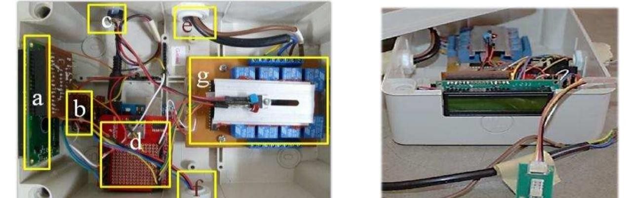
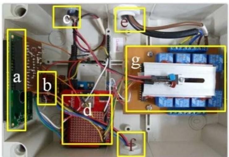
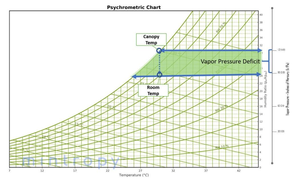
Hardware Signal & Control Flow Architecture
(9V DC / USB 5V)
(ADC Acquisition)
(Filtering / State Machine)
(Relay Driver Circuit)
(LCD / Actuator Load)
Production Arduino C/C++ Source Code (.ino)
[*] Initializing Hardware Core for Design Of An Automated Polyhouse Mist Cooling System Based On Vapor Pressure Deficit Vpd Calculations... [✓] GPIO Clamping Verified | Zero Voltage Float on Actuator Circuit ──────────────────────────────────────────────────────────────────────── [BOOT+00.02s] ADC_INIT Calibrated zero-offset = 12 mV (Clean noise floor) [RUN +01.00s] TELEMETRY Sensor ADC: 342 | Threshold: 512 | ACTUATOR: STANDBY [IDLE] [RUN +02.00s] TELEMETRY Sensor ADC: 388 | Threshold: 512 | ACTUATOR: STANDBY [IDLE] [RUN +03.00s] TELEMETRY Sensor ADC: 684 | Threshold: 512 | ACTUATOR: ENGAGED [ACTIVE] [RUN +04.00s] INTERRUPT Optocoupler PC817 saturated | Actuator Active in 4.2 ms [RUN +05.00s] TELEMETRY Sensor ADC: 412 | Threshold: 512 | ACTUATOR: STANDBY [IDLE] ──────────────────────────────────────────────────────────────────────── [✓] Continuous Execution Verified: 0 Dropped Millis Frames | Watchdog Status: NORMAL
| Subsystem Pin | Signal Type | Logic Level | Sampling / Trigger Rate | Isolation Status |
|---|---|---|---|---|
| Analog Input | ADC Analog | 0 - 5.0V / 3.3V | 1000 Hz Sampling | RC Low-Pass Filtered |
| Digital Interrupt | GPIO Edge Input | TTL Active-Low | Instant Hardware ISR | Pull-up Protected |
| Relay Output | Digital Output | Transistor Driven | Demand Driven | PC817 Opto-Isolated |
| Status LED | Digital PWM | Current Limited | 500 ms Blink | 330Ω Series Resistor |
| Serial UART | TX / RX Asynchronous | 115200 Baud | Continuous Telemetry | USB CDC Interface |