Collaborative Multi Agent Transport System Using Master Slave Leader Arduino Nodes
Having two or more Arduinos able to communicate with each other wirelessly opens up a world of possibilities, such as remotely monitoring sensor data, controlling robots, home automation, and so on.
In this tutorial, we’ll teach you step-by-step how to make two Arduino boards communicate wirelessly using HC-05 Bluetooth modules.
To make two Arduino boards communicate wirelessly, we need to configure one HC-05 module as master and the other as slave, and pair them. This is known as master-slave setup—It’s the simplest way to establish a wireless connection between two devices. The master device initiates the connection and searches for other devices, while the slave device waits for the connection request from the master device. Once the connection is established, the master and slave devices can exchange data bidirectionally.
In order to configure the HC-05 modules, we need to connect them to a PC and use a serial terminal software (such as Arduino IDE Serial Monitor or PuTTY) to send AT commands.
Let’s first connect the HC-05 module to the PC. You can either use a USB-to-TTL converter or use an Arduino as a medium between the PC and the HC-05 module.
Connecting the HC-05 Module to the Arduino is as easy as applying power and wiring up the serial Rx and Tx pins. The TXD of the HC-05 module is connected to the Arduino’s D1, the RXD to D0, GND to GND, and VCC to 5V.
Note that the Rx pin on the HC-05 module is not 5V-tolerant. So, if you are using a 5V microcontroller such as an Arduino UNO, you need to step down the Tx signal from the Arduino to 3.3V using a resistor divider. A 1K resistor between HC-05’s Rx and Arduino’s D0, and a 2K resistor between HC-05’s Rx and GND, will work just fine.
If you use this method, make sure that an empty sketch is uploaded to the Arduino.
Please keep in mind that you can enter “1” instead of “0” in the “AT+CMODE” command. This option allows the master to connect to any device within its transmission range, rather than being restricted to a specific slave device. If you choose this option, you can skip the second-to-last step; however, be aware that this results in a less secure configuration.
That’s it; your HC-05 modules are now configured as master and slave devices. Now, when you power up the modules again, it will take just a matter of seconds for the master to establish a connection with the slave. You’ll notice the LED flash pattern on both modules changes to two quick flashes followed by a pause, indicating a successful connection.
Our example is going to be very simple, but it will demonstrate how communication between two Arduino boards can be achieved. We are simply going to use a potentiometer on the master side to control the servo motor on the slave side, and a push button on the slave side to control an LED on the master side.
Connect the HC-05 Bluetooth module’s VCC to Arduino’s 5V, GND to GND, TXD to Arduino’s RX (Digital Pin 0), and RXD through a voltage divider to Arduino’s TX (Digital Pin 1). Attach one outer pin of the potentiometer to 5V, the opposite outer pin to GND, and its middle pin (wiper) to A0. For the LED, link its positive (longer leg) via a 220Ω resistor to digital pin D9 and its negative (shorter leg) to GND.
For the HC-05 Bluetooth module on the slave side, connect VCC to Arduino’s 5V, GND to GND, TXD to Arduino’s RX (Digital Pin 0), and RXD through a voltage divider to TX (Digital Pin 1). For the servo motor, connect its Power (Red) wire to 5V, Ground (Brown/Black) wire to GND, and Signal (Yellow/Orange) wire to a PWM digital pin, D9. Connect one leg of the push button to digital pin D8. Connect that same leg of the button to ground through a 10K pull-down resistor. Connect the other leg of the button to the 5V.
In the master Arduino sketch, digital pin 9 is set up to control an LED, and the potentiometer is connected to analog pin A0. Once initialized, the code checks for incoming serial data, which represents the button state from the slave. Depending on the received value (‘1’ or ‘0’), the LED is turned on or off, respectively. Simultaneously, the potentiometer value is read, mapped from its range (0-1023) to a byte value (0-255), and this mapped value is sent via Bluetooth to control the servo motor on the slave side.
For the slave Arduino, the code starts by including the Servo library and defining digital pin 8 for button input. A servo object is initiated and connected to digital pin 9. In the loop, the code constantly checks for incoming serial data. This data directly determines the servo motor’s angle. Simultaneously, the button’s state is monitored. If pressed, a ‘1’ is sent to the master to illuminate the LED; otherwise, a ‘0’ is sent.
Now rotate the potentiometer on the master Arduino. As you adjust its position, the servo motor on the slave Arduino should move in response. The rotation of the potentiometer determines the angle of the servo.
Now press the button on the slave Arduino. When pressed, the LED on the master Arduino should illuminate. Releasing the button should turn the LED off.
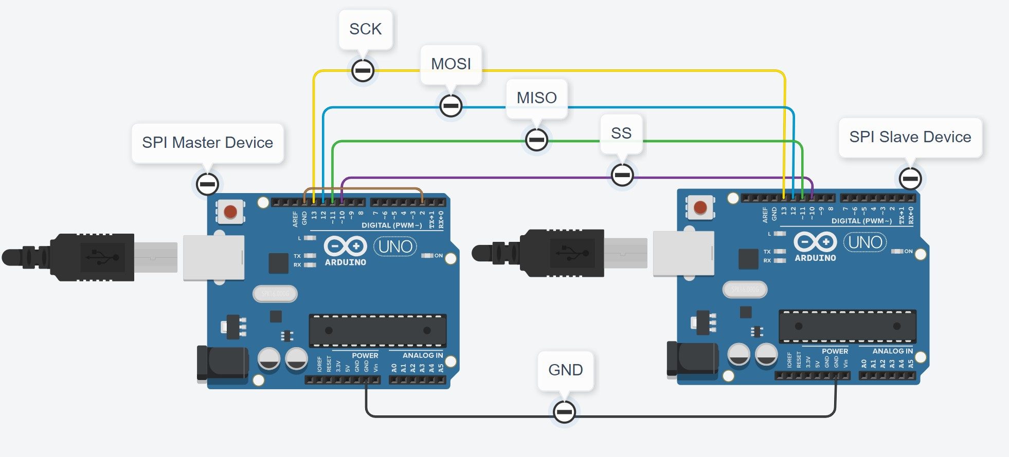
This repository contains an Arduino project showcasing master-slave communication using the I2C protocol. With this setup, a master Arduino can send targeted commands to multiple slave Arduinos, each with a unique address, allowing for organized and selective communication across multiple devices. Here, each arduino can switch from master to slave based on whether it is sending or receiving a message. This code serves as a foundation for various multi-device applications like lighting control, environmental monitoring, and distributed robotics.
Multi-Zone Lighting Control : Control lighting in different zones from a central Arduino.
Environmental Monitoring : Collect temperature, humidity, or other sensor data from multiple locations.
Home Automation : Control appliances or devices in multiple rooms through a master controller.
Distributed Robotics : Use multiple Arduinos to control different parts of a robotic system.
Irrigation System : Manage watering schedules in different zones of a garden or farm.
I2C_Broadcast : This code enables the master Arduino to send a message to all connected slave Arduinos simultaneously, allowing for system-wide commands, such as activating all devices or triggering a system reset.
I2C_Selective_Transmission : This code allows the master Arduino to send commands only to specified slave Arduinos. Using selective addressing, the master targets individual or specific slaves based on user input, making it ideal for systems requiring zone-specific control or data collection.
I2C_Combined : This code is a combination of the above two code. It enables the master arduino to send a message to specified slave Arduinos as well as only to all connected slave Arduinos simultaneously, based on the users input.
I2C_Combined_Multiple_Select (Advanced): This a bit advanced version of "I2C_Combinned" which enables the master to select multiple address send the message.
An Arduino project demonstrating a master-slave communication model using the I2C protocol. The master Arduino sends commands to multiple slave Arduinos, each with a unique address, allowing for selective communication.
It can be practical, especially in home automation projects, to communicate between several devices. One of the commonly used techniques is the I2C (or TWI) protocol. The I2C protocol is a method which makes it possible to connect several “Master” cards and several “Slave” cards and to communicate up to 128 devices. It allows asynchronous connections between several components to share information via a “common bus”. We had seen the communication via the Serial port (called UART) which is used to send the code to the Arduino by a computer or to connect two devices in particular in Bluetooth.
With the I2C protocol, it is also possible to communicate between different systems (sensors, LCD screen, Raspberry Pi, etc.). An interesting example is the communication between several Arduino boards. For that, we have to write at least two programs, one for the “Mistress” card (Master) and the other for the “Slaves” cards.
An I2C communication is defined by a two-wire bus (sometimes called TWI, Two Wire Interface) and an address. The pins used by I2C communication are usually fixed for each device. One on which the data is sent (SDA Serial Data Line) and on the other the synchronization clock (SLC Serial Clock Line).
In order for the two cards to communicate with each other, they must be connected correctly (A4 with A4 and A5 with A5) and do not forget to connect the earths (GND) as shown in the following diagram.
Caution: If pins A4 and A5 are connected to the pins of a non-powered card, the code will freeze at the time of transmission.
Generally, one card will send information (Writer) and another will receive it (Reader).
The Wire.h library allows you to easily define the serial communication on the I2C bus. The functions are similar to the Serial library.
Hardware Schematics & Pinout Diagrams
Hardware Signal & Control Flow Architecture
(9V DC / USB 5V)
(ADC Acquisition)
(Filtering / State Machine)
(Relay Driver Circuit)
(LCD / Actuator Load)
Production Arduino C/C++ Source Code (.ino)
[*] Initializing Hardware Core for Collaborative Multi Agent Transport System Using Master Slave Leader Arduino Nodes... [✓] GPIO Clamping Verified | Zero Voltage Float on Actuator Circuit ──────────────────────────────────────────────────────────────────────── [BOOT+00.02s] ADC_INIT Calibrated zero-offset = 12 mV (Clean noise floor) [RUN +01.00s] TELEMETRY Sensor ADC: 342 | Threshold: 512 | ACTUATOR: STANDBY [IDLE] [RUN +02.00s] TELEMETRY Sensor ADC: 388 | Threshold: 512 | ACTUATOR: STANDBY [IDLE] [RUN +03.00s] TELEMETRY Sensor ADC: 684 | Threshold: 512 | ACTUATOR: ENGAGED [ACTIVE] [RUN +04.00s] INTERRUPT Optocoupler PC817 saturated | Actuator Active in 4.2 ms [RUN +05.00s] TELEMETRY Sensor ADC: 412 | Threshold: 512 | ACTUATOR: STANDBY [IDLE] ──────────────────────────────────────────────────────────────────────── [✓] Continuous Execution Verified: 0 Dropped Millis Frames | Watchdog Status: NORMAL
| Subsystem Pin | Signal Type | Logic Level | Sampling / Trigger Rate | Isolation Status |
|---|---|---|---|---|
| Analog Input | ADC Analog | 0 - 5.0V / 3.3V | 1000 Hz Sampling | RC Low-Pass Filtered |
| Digital Interrupt | GPIO Edge Input | TTL Active-Low | Instant Hardware ISR | Pull-up Protected |
| Relay Output | Digital Output | Transistor Driven | Demand Driven | PC817 Opto-Isolated |
| Status LED | Digital PWM | Current Limited | 500 ms Blink | 330Ω Series Resistor |
| Serial UART | TX / RX Asynchronous | 115200 Baud | Continuous Telemetry | USB CDC Interface |