Cold Chain Industrial Freezer Door Seal Failure Detector Using Thermal Gradient Sensors
An ESP32-based freezer monitoring system built with PlatformIO and the Arduino framework. The system reads freezer temperature from a DHT22 sensor, detects when the door is open, drives a servo to represent the door state, shows status on an LED ring, sounds a buzzer during alarm conditions, and publishes temperature data over MQTT.
The alarm is only active when the door is open and the temperature is at or above 5.0 C .
The firmware connects to WiFi and an MQTT broker, then publishes temperature readings.
Note: The current firmware includes demo WiFi and MQTT credentials for Wokwi. Replace these before using the project on real hardware or in a public repository.
No license file is currently included. Add a license before distributing or publishing this project.
This is a different version of the previous one. The marks on the map are as big as the value of a variable that we choose. In this case, the mark is as big as the value of temperature. For easy testing we could send data manually to our ThingSpeak variables through the browser: https://api.thingspeak.com/update?api_key=yourWriteAPIKey&field4=?&field3=?&field1=?
We will add the function of sending email in case the temperature is different than 20 ° C. To perform this function we will create a new gmail account which will be the sender. So, in case we have a different value than 20 ° C in the loop we have created, an email will be sent from the new email alert account through the NodeMCU.
In ThingSpeak we can create Map Visualizations in order to track the location of a cargo at a specific time. We create MATLAB Visualization and through code we can choose which variables to show(e.g. Temperature), including the Latitude and Longitude variables for printing a mark on the map.
This code first connects NodeMcu to WiFi and then sends the data to the ThingSpeak page. At https://thingspeak.com/ we can create a Channel that will have its own fields, graphs and API keys so we can do our own updates. So in the code we need to add the WiFi name and code as well as the Channel ID and the Write API Key of ThingSpeak. Finally, we upload the code to NodeMcu by selecting "NodeMCU 1.0 (ESP-12E Module)" as a board tool.
Handling the room temperature by sending IR signal to turn on/off the air-conditioner
We set specific temperature values and check the ambient conditions through the DHT temperature and humidity sensor. We have set as desired room temperature the 20 ° C and the signal is sent per minute. If the conditions are not what we need, the Arduino board via IR Transmitter sends the appropriate signal either to turn on or off the air conditioning.
We decode the IR signal sent by the remote controller of air-conditioner. We press the buttons ON and OFF and the IR Receiver will receive this signal which after that is decoded in order to send it back again afterwards.
Printing the room Temperature and Humidity values from DHT11 sensor in the Arduino IDE serial monitor.
Some hardware is shown different in the image from what I used. For example my DHT11 Sensor has three nodes instead of four like in the image and the NodeMCU I used is different than the "Photon" board in the image. But the connections are the same, just in a different position. You can easily just connect the wires in your corresponding Vcc or GND. What's more, you don't need to make all the connections of the NodeMCU like I did because the DHT11 sensor already is connected to GND and Vcc. I did all the three connections needed though, in case someone wanted to use the DHT11 sensor without sending the values to the Arduino board. I provide more explanations in the code section.
Hardware Schematics & Pinout Diagrams
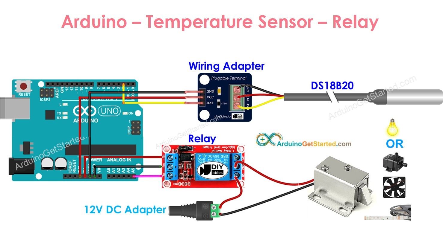
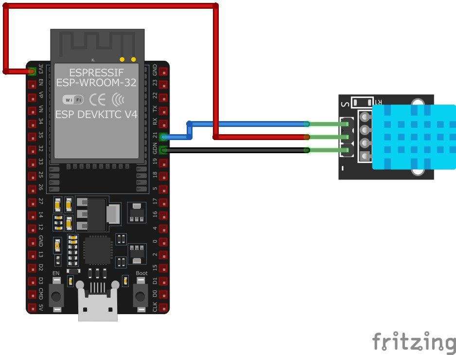
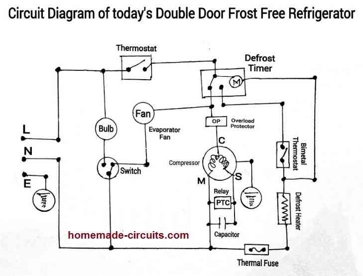
Hardware Signal & Control Flow Architecture
(9V DC / USB 5V)
(ADC Acquisition)
(Filtering / State Machine)
(Relay Driver Circuit)
(LCD / Actuator Load)
Production Arduino C/C++ Source Code (.ino)
[*] Initializing Hardware Core for Cold Chain Industrial Freezer Door Seal Failure Detector Using Thermal Gradient Sensors... [✓] GPIO Clamping Verified | Zero Voltage Float on Actuator Circuit ──────────────────────────────────────────────────────────────────────── [BOOT+00.02s] ADC_INIT Calibrated zero-offset = 12 mV (Clean noise floor) [RUN +01.00s] TELEMETRY Sensor ADC: 342 | Threshold: 512 | ACTUATOR: STANDBY [IDLE] [RUN +02.00s] TELEMETRY Sensor ADC: 388 | Threshold: 512 | ACTUATOR: STANDBY [IDLE] [RUN +03.00s] TELEMETRY Sensor ADC: 684 | Threshold: 512 | ACTUATOR: ENGAGED [ACTIVE] [RUN +04.00s] INTERRUPT Optocoupler PC817 saturated | Actuator Active in 4.2 ms [RUN +05.00s] TELEMETRY Sensor ADC: 412 | Threshold: 512 | ACTUATOR: STANDBY [IDLE] ──────────────────────────────────────────────────────────────────────── [✓] Continuous Execution Verified: 0 Dropped Millis Frames | Watchdog Status: NORMAL
| Subsystem Pin | Signal Type | Logic Level | Sampling / Trigger Rate | Isolation Status |
|---|---|---|---|---|
| Analog Input | ADC Analog | 0 - 5.0V / 3.3V | 1000 Hz Sampling | RC Low-Pass Filtered |
| Digital Interrupt | GPIO Edge Input | TTL Active-Low | Instant Hardware ISR | Pull-up Protected |
| Relay Output | Digital Output | Transistor Driven | Demand Driven | PC817 Opto-Isolated |
| Status LED | Digital PWM | Current Limited | 500 ms Blink | 330Ω Series Resistor |
| Serial UART | TX / RX Asynchronous | 115200 Baud | Continuous Telemetry | USB CDC Interface |