Chemical Storage Tank Dual Point Ultrasonic And Hydrostatic Level Redundancy System
An Arduino-based Smart Water Tank Level Monitoring System that automatically monitors the water level in a storage tank using an HC-SR04 ultrasonic sensor. The system displays the current water level status on a 16×2 I2C LCD, provides visual indication using LEDs, automatically controls a water pump through a relay module, and alerts the user with a buzzer when the tank becomes full.
This project is designed as a simple, low-cost automation system suitable for learning embedded systems, Arduino programming, and basic industrial automation concepts. It can also be used as a foundation for more advanced IoT-based smart water management systems.
Water tanks require regular monitoring to avoid overflow, water wastage, and dry running of pumps. Manual monitoring is time-consuming and often unreliable. This project solves these problems by continuously measuring the water level inside a tank using an ultrasonic sensor.
The Arduino processes the sensor data and determines whether the water level is Low, Medium, or Full. Based on the detected level, the system automatically controls the water pump, updates the LCD display, changes the LED indicators, and activates a buzzer when the tank reaches its full capacity.
The project demonstrates the practical implementation of sensors, displays, relays, actuators, and embedded programming in a single automation system.
#Simulation link: https://www.tinkercad.com/things/eFw002WPhdv-smart-watertank-monitoring-system?sharecode=R3O2bHofAafceAGw8azrSZfavPob8a8QVY6mEtWGeBs
The HC-SR04 ultrasonic sensor continuously measures the distance between the sensor and the water surface.
According to the measured value, the system classifies the water level into one of three stages:
If the ultrasonic sensor does not return a valid reading, the system displays a sensor fault message and turns OFF the motor for safety.
These values can be modified in the Arduino code to match the dimensions of any water tank.
Connect all hardware components according to the circuit connections provided above.
Change the distance between the ultrasonic sensor and the object (or water surface) to observe the system automatically switching between different water levels.
Smart Water Tank Level Monitoring System using Arduino UNO and HC-SR04 ultrasonic sensor. The system monitors water level in real time, displays the status on a 16×2 I2C LCD, controls a water pump automatically through a relay, indicates levels using LEDs, and alerts when the tank is full with a buzzer.
This project explains how to build a fully automatic ultrasonic water level controller where the water pump motor starts automatically when the tank level goes below a preset LOW level and stops automatically when the tank becomes FULL. The whole system is wireless , reliable, and there are no corrosion problems because the ultrasonic sensor never touches the water at any point.
The design uses an HC-SR04 ultrasonic sensor to measure the water level, Arduino units at both Tx and Rx sides for processing, nRF24L01 RF modules for wireless communication between tank and pump, a relay driver stage to control the water pump motor, and LED indicators with a buzzer to show visual and audible status.
Traditional water level systems using float switches or probe-based sensors usually suffer from corrosion, scaling buildup, mechanical wear, and false triggering over time.
An ultrasonic sensor avoids all these problems because it does not come in contact with water. It simply measures the distance from the sensor to the water surface, and the Arduino then converts this distance value into the actual water level.
The system is divided into two main parts, one at the tank side and the other at the pump side.
At the tank side, the ultrasonic sensor is mounted at the top of the tank facing the water surface. The Arduino measures the water level using the sensor data and then sends the water level status wirelessly to the receiver unit.
At the pump side, the receiver unit receives the water level status data. Based on this information, it controls the LED indicators and buzzer and also drives a relay to switch the water pump ON or OFF automatically.
Simple reason, it does ultrasonic conversion properly, so readings stay accurate, and it does what it is supposed to do.
Here tank size does not really matter here, you just change two values and it is done. No need to redesign anything, so it fits small tank big tank, whatever you have.
There is timeout protection also, so if sensor fails or gets stuck then system does not keep waiting indefinitely, it safely exits.
Relay chattering is avoided in this design, switching happens only at LOW and FULL, not in between, so relay stays calm without any clicking noise, so there is no damage over time.
Sensor must face straight down, do not tilt it, otherwise readings could go wrong.
Keep around 5–10 cm clearance from tank walls, since reflections can confuse the sensor, and then values can jump.
Please avoid steam and water droplets on sensor face because that can finish of accuracy fast, and then system starts behaving rather weird.
If you want the Transmitter to work with SR04M-2, instead of the ultrasonic sensor then you can use the following modified version of the code:
If you want to attach an LCD for viewing the water levels on the LCD, you can modify the above receiver code as follows:
Relay COM goes to Phase input, then Relay NO goes to pump phase wire, so pump switches ON and OFF from relay.
Neutral wire goes directly to pump, no switching there. Mains voltage is dangerous, so if you are unsure at any point, then consult a qualified electrician, do not take risk.
Mount the HC-SR04 exactly at the center of the tank lid, not here and there. Keep minimum 5–10 cm clearance from walls, otherwise readings go wrong.
No water contact sensors, so nothing corrodes. Long wireless range, works comfortably. Fully automatic, no manual switching. No false triggering, readings stay stable.
Suitable for overhead tanks, common use. Easily expandable, you can add more features later.
This ultrasonic water level controller is reliable, scalable and works well for domestic and industrial water tanks. With simple parameter changes in the code, the same design can be used for any tank height or shape, so no redesign needed.
If you build this project, then feel free to share your experience or ask for modifications in the comments.
Full string match is used, so no false trigger happens, random noise will not confuse it....
Use external 3.3V regulator, do not depend on weak onboard supply, since that causes trouble.
Add 10µF capacitor across nRF VCC-GND, this helps stability, otherwise module may behave strange.
When testing, use PA_LOW but when final setup is done then switch to PA_MAX for long range.
Keep antennas in line of sight if you want near 500m range, if obstacles come then range drops, so placement matters.
hi sir…..thank you for your post water controller with rf24 and reed sensor. this code is working perfectly. but i need some improvement plz dont mind. in this code pump on at half d2. plz make it half d2 only led on. pump off. pump on at water less from low level with pin A3. off at full as you did. tank side pin d8 is normal blink as status. if RF SIGNAL OK. AND make it like if RF signal lost status led fast blink. SAME IN PUMP SIDE If RF signal ok circut work as logic code. if RF signal ok then normal blink. if RF SIGNAL LOST then status led fast blink and pump off.
Thanks Ghulam, glad it is working for you. Please check the bottom of the above article for the new updates, according to your this requirements.
sir if with this sensor system will not proper stable then its better to use reed sensor. with same setup. tank side pinout rf24 a1,a2 full d5 half d4 low d3 make d8 led blink status logic when level low or less then low. pump on. when reached at low. led low level at pump side D3 glow. level at half led glow D2 pump side. at full all led glows and pump off. when level less from full. led pump side A3 off. keep pump off. water less from half d2 pump side off. pump off. when reached to low d3 led glow and pump on. if water level less than low d3 led off. due to power failure. when power back if water level at low or less then low. pump on. hope you got my logic. pump side rf24 a1,a2 make a4 led blink as status
Hardware Schematics & Pinout Diagrams
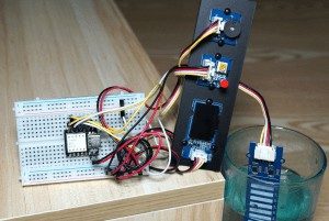
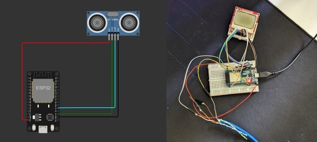
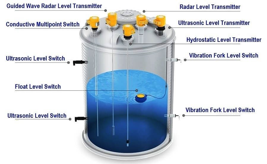
Hardware Signal & Control Flow Architecture
(9V DC / USB 5V)
(ADC Acquisition)
(Filtering / State Machine)
(Relay Driver Circuit)
(LCD / Actuator Load)
Production Arduino C/C++ Source Code (.ino)
[*] Initializing Hardware Core for Chemical Storage Tank Dual Point Ultrasonic And Hydrostatic Level Redundancy System... [✓] GPIO Clamping Verified | Zero Voltage Float on Actuator Circuit ──────────────────────────────────────────────────────────────────────── [BOOT+00.02s] ADC_INIT Calibrated zero-offset = 12 mV (Clean noise floor) [RUN +01.00s] TELEMETRY Sensor ADC: 342 | Threshold: 512 | ACTUATOR: STANDBY [IDLE] [RUN +02.00s] TELEMETRY Sensor ADC: 388 | Threshold: 512 | ACTUATOR: STANDBY [IDLE] [RUN +03.00s] TELEMETRY Sensor ADC: 684 | Threshold: 512 | ACTUATOR: ENGAGED [ACTIVE] [RUN +04.00s] INTERRUPT Optocoupler PC817 saturated | Actuator Active in 4.2 ms [RUN +05.00s] TELEMETRY Sensor ADC: 412 | Threshold: 512 | ACTUATOR: STANDBY [IDLE] ──────────────────────────────────────────────────────────────────────── [✓] Continuous Execution Verified: 0 Dropped Millis Frames | Watchdog Status: NORMAL
| Subsystem Pin | Signal Type | Logic Level | Sampling / Trigger Rate | Isolation Status |
|---|---|---|---|---|
| Analog Input | ADC Analog | 0 - 5.0V / 3.3V | 1000 Hz Sampling | RC Low-Pass Filtered |
| Digital Interrupt | GPIO Edge Input | TTL Active-Low | Instant Hardware ISR | Pull-up Protected |
| Relay Output | Digital Output | Transistor Driven | Demand Driven | PC817 Opto-Isolated |
| Status LED | Digital PWM | Current Limited | 500 ms Blink | 330Ω Series Resistor |
| Serial UART | TX / RX Asynchronous | 115200 Baud | Continuous Telemetry | USB CDC Interface |