Bio Inspired Hexapod Walking Robot With Inverse Kinematic Wave Gait Execution Using Arduino
This project presents the design and implementation of a fully actuated 18-degree-of-freedom (DOF) hexapod robot capable of stable and coordinated locomotion. The system combines embedded control, inverse kinematics, and high-level motion planning to achieve smooth walking using biologically inspired gait patterns.
The robot is designed to address common challenges in multi-legged systems, including servo synchronization, real-time control, and scalable architecture for future autonomy.
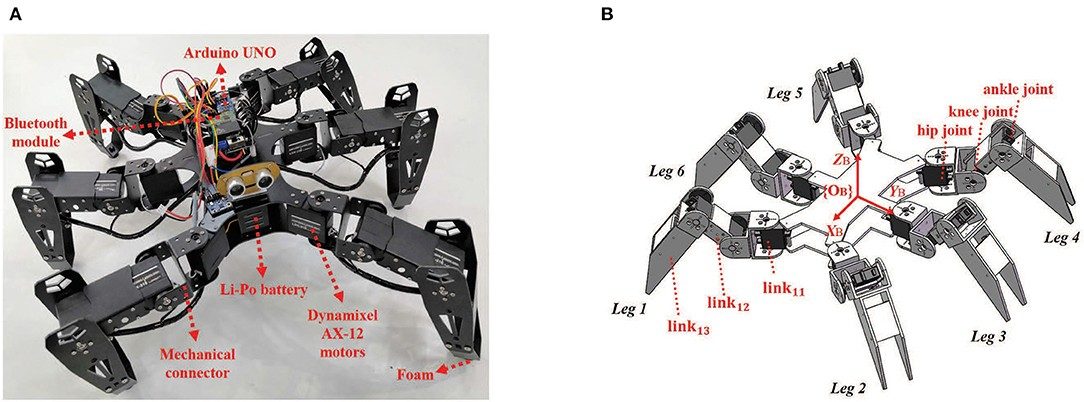
Each leg is modeled as a 3-DOF manipulator. Inverse kinematics is used to compute joint angles required to position the foot in 3D space.
18-DOF hexapod robot with inverse kinematics, real-time gait control, and synchronized servo actuation using PCA9685, built on Arduino and ROS.
A six-legged hexapod robot with 18° of freedom , designed for dynamic locomotion, terrain adaptability, and autonomous control. Each leg is powered by three servo motors to enable complex, multi-axis movements for walking, turning, and balancing.
This project demonstrates bio-inspired robotics and explores inverse kinematics , wireless control , and embedded motion algorithms using Arduino.
The hexapod’s walking behavior is based on tripod gait , where three legs stay in contact with the ground while the other three move forward. Inverse kinematics equations compute joint angles for each servo in real time, ensuring synchronized, stable motion across uneven terrain.
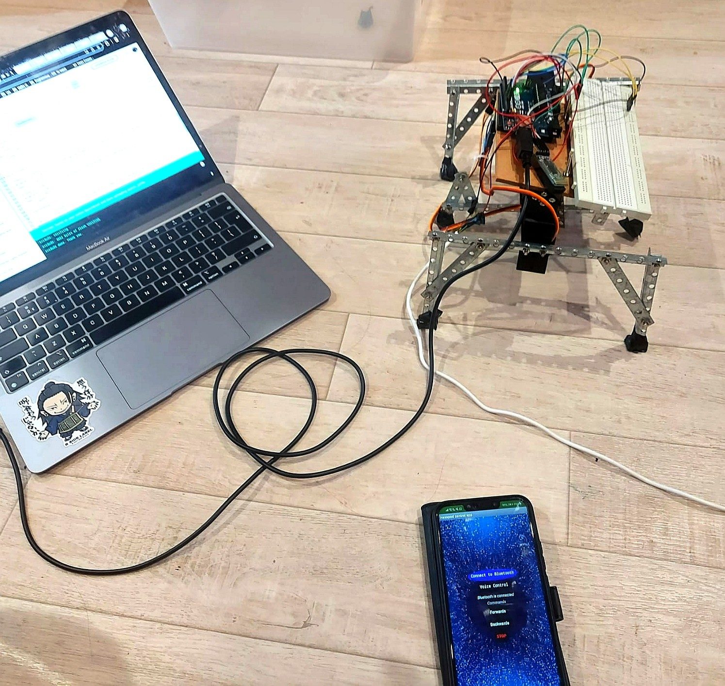
Wireless data from the remote (Arduino Nano) is transmitted via nRF24L01 to the hexapod (Arduino Mega) , which interprets the joystick input and adjusts leg positions accordingly.
Designing and developing a six-legged hexapod robot with 18° of freedom, each leg driven by 3 servo motors for precise multi-axis motion. Arduino-based control enables gait generation, balance, and terrain adaptability. Focused on inverse kinematics, wireless control, and autonomous exploration.
Master hexapod walking: From stable tripod gait biology to adaptive control with inverse kinematics. Build smarter robots.
Hexapod robots serve as excellent platforms for exploring bionics and motion control algorithms. One fundamental and efficient walking pattern for such robots is the tripod gait. This article explains its biological inspiration, engineering implementation, and how modern approaches like inverse kinematics (IK) overcome the limitations of traditional pre-programmed methods. We'll use general hexapod concepts for illustration, applicable to platforms like the MiniHexa .
Observe an insect walking—it doesn't move all 6 legs at once. Instead, it coordinates them into two alternating sets of three, forming stable tripods. Typically, legs are grouped as (Left Front, Left Rear, Right Middle) and (Right Front, Right Rear, Left Middle).
While one tripod is on the ground (stance phase), providing a stable, three-point support base, the other tripod is in the air (swing phase), moving forward. They then switch roles. This pattern offers high static stability, allowing the robot to remain balanced without complex dynamic control, making it robust on varied terrain.
Traditionally, implementing gaits like this often relied on pre-recorded motion sequences.
The "Frame-by-Frame" Method: Developers would manually define every servo angle for each phase of the step cycle, creating a fixed animation. While functional, this approach is rigid. The robot cannot dynamically adjust its stride length, turn smoothly, or change body height in real-time. It simply replays a recording, which limits adaptability.
A more advanced and flexible method uses Inverse Kinematics (IK). Think of reaching for a cup: your brain effortlessly calculates the necessary joint angles for your arm. IK performs this calculation for a robot.
For a hexapod, you don't program individual leg joint angles. Instead, you define a high-level goal: "Move the body forward at 5 cm/s" or "Turn left." The IK algorithm then works backwards:
1. It calculates the desired foot tip trajectory in 3D space for each leg during its swing phase.
2. It solves the kinematic equations for each leg to determine the exact angles required at the hip, femur, and tibia joints to achieve that tip position.
If you're building or programming a hexapod, here's how to approach implementing an IK-based tripod gait:
The tripod gait exemplifies how biological principles inspire robust robotic solutions. Moving from fixed sequences to IK-based control represents a significant leap, transforming a hexapod from a simple automaton into an adaptive, programmable platform.
Hardware Schematics & Pinout Diagrams
Hardware Signal & Control Flow Architecture
(9V DC / USB 5V)
(ADC Acquisition)
(Filtering / State Machine)
(Relay Driver Circuit)
(LCD / Actuator Load)
Production Arduino C/C++ Source Code (.ino)
[*] Initializing Hardware Core for Bio Inspired Hexapod Walking Robot With Inverse Kinematic Wave Gait Execution Using Arduino... [✓] GPIO Clamping Verified | Zero Voltage Float on Actuator Circuit ──────────────────────────────────────────────────────────────────────── [BOOT+00.02s] ADC_INIT Calibrated zero-offset = 12 mV (Clean noise floor) [RUN +01.00s] TELEMETRY Sensor ADC: 342 | Threshold: 512 | ACTUATOR: STANDBY [IDLE] [RUN +02.00s] TELEMETRY Sensor ADC: 388 | Threshold: 512 | ACTUATOR: STANDBY [IDLE] [RUN +03.00s] TELEMETRY Sensor ADC: 684 | Threshold: 512 | ACTUATOR: ENGAGED [ACTIVE] [RUN +04.00s] INTERRUPT Optocoupler PC817 saturated | Actuator Active in 4.2 ms [RUN +05.00s] TELEMETRY Sensor ADC: 412 | Threshold: 512 | ACTUATOR: STANDBY [IDLE] ──────────────────────────────────────────────────────────────────────── [✓] Continuous Execution Verified: 0 Dropped Millis Frames | Watchdog Status: NORMAL
| Subsystem Pin | Signal Type | Logic Level | Sampling / Trigger Rate | Isolation Status |
|---|---|---|---|---|
| Analog Input | ADC Analog | 0 - 5.0V / 3.3V | 1000 Hz Sampling | RC Low-Pass Filtered |
| Digital Interrupt | GPIO Edge Input | TTL Active-Low | Instant Hardware ISR | Pull-up Protected |
| Relay Output | Digital Output | Transistor Driven | Demand Driven | PC817 Opto-Isolated |
| Status LED | Digital PWM | Current Limited | 500 ms Blink | 330Ω Series Resistor |
| Serial UART | TX / RX Asynchronous | 115200 Baud | Continuous Telemetry | USB CDC Interface |