Bathroom Scalding Prevention Valve With Instant Hot Water Cut Off Controlled By Arduino
The Smart Shower Management System is an Arduino control system designed for reducing water use and energy costs during showers. It turns off the hot water flow after a pre-set and configurable time. By limiting shower time, it ensures hot showers for everyone, while contributing for major water savings, depending on the current use. In the event of a power outage, both hot and cold water are able to flow, since the electrovalve should be a normally-open valve.
The components required for this project are the following (in parenthesis I state the models that I used in my implementation):
The high-level installation of the Smart Shower is highlighted in the figure below:
The Arduino code implements a state machine controller. By measuring the flow at every second and monitoring the time, it controls the transitions between states and allows for a smart shower with 2 exit conditions (described below)
Moreover, FLOW_THRESHOLD denotes flow-rate threshold to trigger transition from IDLE to BATH state. When the flow sensor readings are above FLOW_THRESHOLD , water is considered to be flowing. This threshold may be set to a certain positive number, in order to discard the processing of residual flow.
Note that all these definitions can be easily tuned and upgraded to the Arduino board.
The program starts in IDLE state and measures the flow rate with a frequency of 1Hz. If the flow at a given time is greater than FLOW_THRESHOLD , then it activates a transition flag. If after TRANSITION_TIME time, the flow is still greater than the threshold, then the program transitions to BATH state, otherwise it keeps in IDLE state. This is to prevent triggering a bath cycle for short periods of water use (which may be related to cleaning purposes, for example).
When the program reaches the BATH state, it may transition to the RECOVERY state when one of two conditions is satisfied:
Note that to get the total period of hot-water availability for a single shower, you also need to take into account the transition time from IDLE to BATH (specified by the TRANSITION_TIME constant).
In any case, when the bath time is ending, the user is warned. During the last WARN_TIME seconds in the BATH state, the buzzer starts beeping and the green LED starts blinking.
The parameters described above can be easily configured in main.ino . All the tunable parameters can be found inside the USER DEFINITIONS section placed at the beginning of the file.
After making the intended changes, the program needs to be re-uploaded to the Arduino board.
I put the Arduino, the breadboard, the power supply and all the wires inside a protection box. I made 2 small holes in the box to place the LEDs and another one to place the buzzer. The solenoid valve and the flow sensor are then placed in hot-water pipe system, as shown in the bottom figure.
If you have any questions, doubts, or need further assistance regarding this Arduino project, feel free to contact me:
Please keep in mind that while I strive to provide support and assistance, I may not be able to respond immediately. Kindly allow for a reasonable amount of time for me to address your inquiries.
Your feedback and suggestions for improving this Arduino project are also welcomed. If you encounter any issues or discover bugs, please consider opening an issue on the project's GitHub repository so that it can be tracked and addressed effectively.
Thank you for your interest in this project, and I appreciate your understanding and cooperation in following the recommended communication channels outlined above.
Wire, code, and debug an Arduino solenoid valve circuit. Includes MOSFET driver selection, pin mapping, non-blocking code, and inductive kickback fixes.
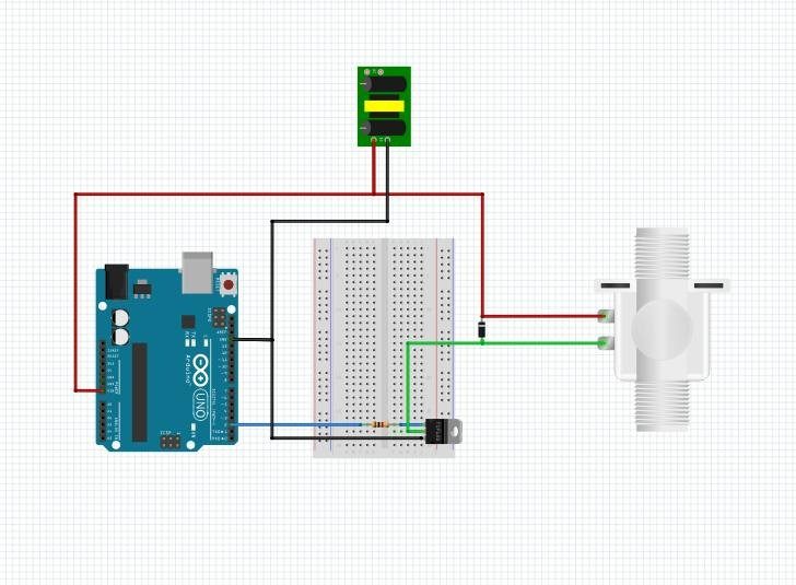
An Arduino GPIO pin outputs 5V at a maximum safe continuous current of 20mA. A standard 12V water or air solenoid valve draws between 1A and 2A. You cannot wire a solenoid directly to an Arduino pin; doing so will instantly destroy the ATmega328P microcontroller. You need a driver circuit.
This build assumes a standard 12V DC brass water valve. Prices are approximate based on 2026 component market rates.
Safety Note: While 12V DC is safe from an electrocution standpoint, a 1.2A continuous current will melt standard 24 AWG breadboard jumper wires over time. Use at least 18 AWG stranded wire for the 12V power loop (PSU to Solenoid to MOSFET Drain), and solder the connections if this is a permanent installation.
This code targets the Arduino Uno R3 (ATmega328P) . It uses a non-blocking millis timer to pulse the solenoid and includes a critical safety feature: a maximum runtime limit. If your code logic hangs or a sensor fails, the solenoid will automatically shut off to prevent flooding or coil burnout.
The most common failure mode in solenoid circuits is the Arduino resetting when the solenoid fires . On the Arduino Uno R3, this manifests as the Serial monitor clearing and re-printing the setup initialization text. If you swap to an ESP32, the serial monitor will output the exact error string: Brownout detector was triggered followed by rst cause:4 .
This happens because inductive kickback or voltage sag on the 12V rail is coupling back into the Arduino's 5V logic rail, triggering the microcontroller's internal Brownout Detector (BOD). Check these three things in order:
The Fix: Verify the 1N4007 diode is physically across the solenoid coil (not across the MOSFET). Ensure the silver stripe (cathode) faces the 12V positive wire. If the diode is backwards, it acts as a dead short when the MOSFET turns on, causing the PSU to fold back its voltage, which starves the Arduino of power and causes a brownout reset.
The Fix: Check the part number printed on your transistor. If it says IRF520 or IRFZ44N , throw it in the bin and buy an IRLZ44N (the 'L' stands for Logic-level). Standard MOSFETs require 10V on the gate to fully open. Driven by a 5V Arduino, they operate in their linear (high-resistance) region. They will get blisteringly hot, fail to pass enough current to pull in the solenoid, and can cause ground-bounce that resets the Arduino. (Reference the Arduino transistor guide for more on Vgs thresholds).
The Fix: Measure the voltage between the Arduino GND pin and the 12V PSU GND terminal with a multimeter while the solenoid is firing. It should read < 0.1V. If it reads higher, your ground wire is too thin. Furthermore, ensure your 12V PSU is rated for at least 2A. A 500mA PSU will experience severe voltage droop when the solenoid's inrush current hits, collapsing the 5V regulator on the Arduino board.
If you don't want to deal with raw MOSFETs, gate resistors, and loose diodes, simplify the build by using a pre-assembled 5V Optocoupler Relay Module (featuring the Songle SRD-05VDC-SL-C relay). Wiring: Connect VCC to Arduino 5V, GND to Arduino GND, and IN to D9. Solenoid Loop: Wire the 12V PSU and solenoid through the relay's COM (Common) and NO (Normally Open) screw terminals. Trade-off: The relay module includes its own built-in flyback diode and optocoupler isolation, making it virtually bulletproof against brownouts. However, mechanical relays are rated for roughly 100,000 click cycles and are louder than a solid-state MOSFET.
To turn this manual push-button circuit into an automated irrigation system, add a DS3231 I2C Real Time Clock (RTC) module. Wire the DS3231 SDA to A4 and SCL to A5 on the Uno R3. Use the RTClib library to read the current time. Add logic to the loop to trigger the openSolenoid function at specific hours (e.g., 06:00 AM and 06:00 PM). Pro-Tip: Add a soil moisture sensor (analog output to A0) and implement hysteresis. Only allow the RTC to open the solenoid if the soil moisture reading is below 30%, preventing overwatering during rain events.
Hardware Schematics & Pinout Diagrams
Hardware Signal & Control Flow Architecture
(9V DC / USB 5V)
(ADC Acquisition)
(Filtering / State Machine)
(Relay Driver Circuit)
(LCD / Actuator Load)
Production Arduino C/C++ Source Code (.ino)
[*] Initializing Hardware Core for Bathroom Scalding Prevention Valve With Instant Hot Water Cut Off Controlled By Arduino... [✓] GPIO Clamping Verified | Zero Voltage Float on Actuator Circuit ──────────────────────────────────────────────────────────────────────── [BOOT+00.02s] ADC_INIT Calibrated zero-offset = 12 mV (Clean noise floor) [RUN +01.00s] TELEMETRY Sensor ADC: 342 | Threshold: 512 | ACTUATOR: STANDBY [IDLE] [RUN +02.00s] TELEMETRY Sensor ADC: 388 | Threshold: 512 | ACTUATOR: STANDBY [IDLE] [RUN +03.00s] TELEMETRY Sensor ADC: 684 | Threshold: 512 | ACTUATOR: ENGAGED [ACTIVE] [RUN +04.00s] INTERRUPT Optocoupler PC817 saturated | Actuator Active in 4.2 ms [RUN +05.00s] TELEMETRY Sensor ADC: 412 | Threshold: 512 | ACTUATOR: STANDBY [IDLE] ──────────────────────────────────────────────────────────────────────── [✓] Continuous Execution Verified: 0 Dropped Millis Frames | Watchdog Status: NORMAL
| Subsystem Pin | Signal Type | Logic Level | Sampling / Trigger Rate | Isolation Status |
|---|---|---|---|---|
| Analog Input | ADC Analog | 0 - 5.0V / 3.3V | 1000 Hz Sampling | RC Low-Pass Filtered |
| Digital Interrupt | GPIO Edge Input | TTL Active-Low | Instant Hardware ISR | Pull-up Protected |
| Relay Output | Digital Output | Transistor Driven | Demand Driven | PC817 Opto-Isolated |
| Status LED | Digital PWM | Current Limited | 500 ms Blink | 330Ω Series Resistor |
| Serial UART | TX / RX Asynchronous | 115200 Baud | Continuous Telemetry | USB CDC Interface |