Autonomous Water Quality Profiling Winch System For Reservoirs Controlled By Arduino
An IoT-based autonomous robotic system designed for real-time water quality monitoring and environmental analysis.
Water pollution monitoring is traditionally performed through manual sampling and laboratory testing, which can be time-consuming and expensive.
This project introduces a low-cost autonomous robotic system capable of monitoring water quality parameters in real time and transmitting data to a cloud dashboard.
The robot can automatically collect and analyze environmental data from water bodies and visualize it through an IoT-based monitoring system .
This project was developed as a Final Year Research Project at Wayamba University of Sri Lanka and was presented at the ASRITE Research Symposium .
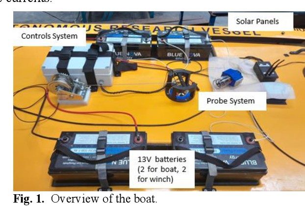
The final system consists of a floating robotic platform equipped with sensors, wireless communication modules, and an IoT dashboard for monitoring environmental data.
The system architecture integrates hardware sensors, wireless communication, cloud data processing, and a real-time dashboard.
The mechanical structure was designed using SolidWorks with a twin catamaran hull design to provide stability in water.
A custom electronic circuit was designed to integrate sensors, communication modules, and power management.
To reduce fabrication cost and improve manufacturing efficiency, both boards were panelized into a single PCB fabrication panel .
The PCB layouts were designed using Altium Designer , including optimized routing, ground planes, and sensor interface isolation.
The final PCB boards were fabricated using FR4 double-layer boards , improving durability, signal stability, and compact system integration.
The system includes a real-time IoT dashboard displaying sensor readings and historical environmental data.
The real-time monitoring dashboard for the Autonomous Water Quality Monitoring System is deployed online and can be accessed below.
This dashboard displays real-time sensor data, and water quality analysis collected by the robotic monitoring system.
Degree Program B.Sc. (Joint Major) – Electronics and Computing & Information Systems
Project Supervisor Eng. S.R.L. Gunawardhana Department of Electronics Wayamba University of Sri Lanka
An autonomous robotic system designed for real-time water quality monitoring with IoT integration and depth profiling.
I used an old test tube I had to make this. I poked holes on either end of the tube and inserted wires from either end. Finally, to hold the wires in place, I attached some putty.
Hardware Schematics & Pinout Diagrams
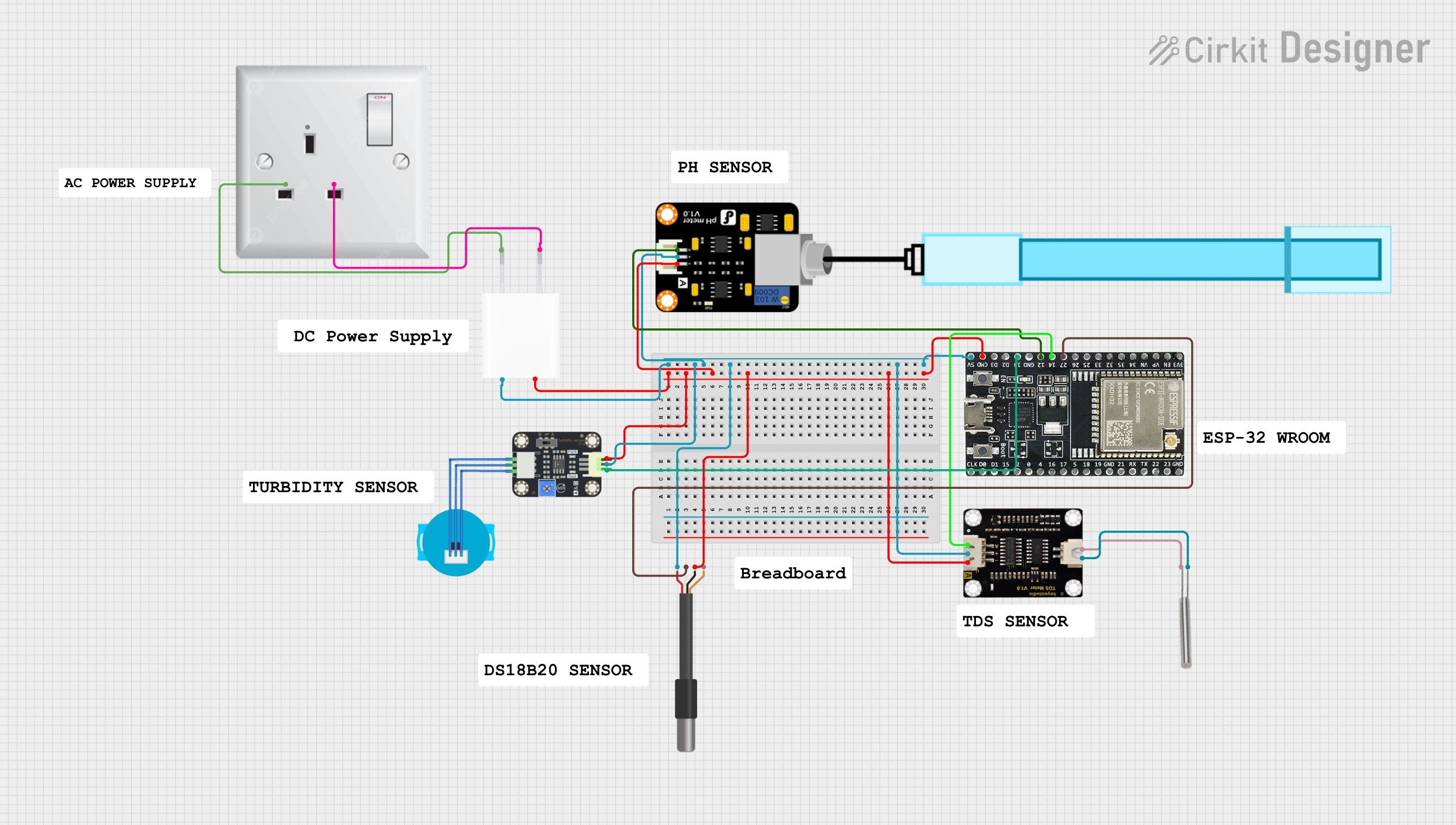
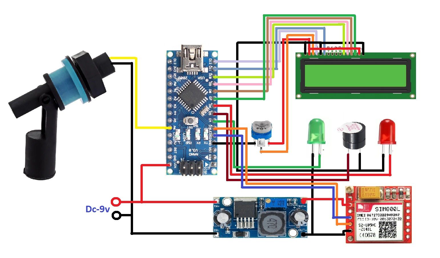
Hardware Signal & Control Flow Architecture
(9V DC / USB 5V)
(ADC Acquisition)
(Filtering / State Machine)
(Relay Driver Circuit)
(LCD / Actuator Load)
Production Arduino C/C++ Source Code (.ino)
[*] Initializing Hardware Core for Autonomous Water Quality Profiling Winch System For Reservoirs Controlled By Arduino... [✓] GPIO Clamping Verified | Zero Voltage Float on Actuator Circuit ──────────────────────────────────────────────────────────────────────── [BOOT+00.02s] ADC_INIT Calibrated zero-offset = 12 mV (Clean noise floor) [RUN +01.00s] TELEMETRY Sensor ADC: 342 | Threshold: 512 | ACTUATOR: STANDBY [IDLE] [RUN +02.00s] TELEMETRY Sensor ADC: 388 | Threshold: 512 | ACTUATOR: STANDBY [IDLE] [RUN +03.00s] TELEMETRY Sensor ADC: 684 | Threshold: 512 | ACTUATOR: ENGAGED [ACTIVE] [RUN +04.00s] INTERRUPT Optocoupler PC817 saturated | Actuator Active in 4.2 ms [RUN +05.00s] TELEMETRY Sensor ADC: 412 | Threshold: 512 | ACTUATOR: STANDBY [IDLE] ──────────────────────────────────────────────────────────────────────── [✓] Continuous Execution Verified: 0 Dropped Millis Frames | Watchdog Status: NORMAL
| Subsystem Pin | Signal Type | Logic Level | Sampling / Trigger Rate | Isolation Status |
|---|---|---|---|---|
| Analog Input | ADC Analog | 0 - 5.0V / 3.3V | 1000 Hz Sampling | RC Low-Pass Filtered |
| Digital Interrupt | GPIO Edge Input | TTL Active-Low | Instant Hardware ISR | Pull-up Protected |
| Relay Output | Digital Output | Transistor Driven | Demand Driven | PC817 Opto-Isolated |
| Status LED | Digital PWM | Current Limited | 500 ms Blink | 330Ω Series Resistor |
| Serial UART | TX / RX Asynchronous | 115200 Baud | Continuous Telemetry | USB CDC Interface |