Autonomous Lawn Mower Robot With Boundary Wire Sensing And Ultrasonic Collision Mitigation
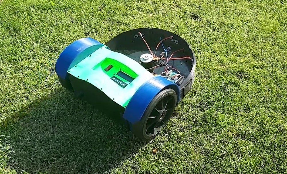
I am building and programming a robotic lawn mower controlled by an Arduino Uno R4. To start with, the mower moves using ultrasonic sensors, if it detects an object it wil change route. The robot will be made of aluminium. It will be battery powered and i am reusing motors from a recycled robot.
here is an extended description: We start with 240V AC from the mains, which goes directly to the charging station. Inside the charging station, it is converted to a lower voltage (24V DC or 12V DC, depending on further research, such as the required motor power, battery specifications, and the availability of components).
The charging station also serves as the base for transmitting the signal through the boundary wire.
The converted DC voltage is transferred from the charging station to the battery via a contact interface between the robot and the station.
The battery is directly connected to three H-bridges, which drive the two wheel motors and the motor for the cutting blade.
A 5V step-down converter is also connected to the battery to power the Arduino (UNO R4 WiFi). Additionally, a voltage divider is placed between the battery and the Arduino, allowing the Arduino to measure and calculate the battery percentage.
The Arduino will be programmed so that the robot mower moves in a random pattern within the area defined by the boundary wire. It also controls the motors via the H-bridges.
Apart from the H-bridges, there is one additional output: an LCD used as part of the user interface. This provides the user with information such as error codes and battery percentage.
The user interface also includes start and stop buttons to control the operation of the robot.
To ensure smooth navigation, the robot is equipped with four sensors: a boundary wire receiver module and three ultrasonic sensors. These detect when the robot approaches an obstacle and allow it to adjust its path if necessary.
In preparation for future expansion, an Arduino UNO R4 WiFi has been selected, enabling the possibility to control and monitor the robot via a smartphone app.
A GPS module is also planned, allowing the robot to follow more structured patterns (such as straight lines) and potentially operate without a boundary wire. In combination with the GPS module, a compass module will be included so the robot can determine its orientation and improve navigation accuracy.
The mower operates using a boundary wire that emits an electrical signal. This signal is detected by the mower, ensuring it automatically stays within the designated area. As an extension, I am adding WiFi control
In this Robotic project, we will build an Automatic Grass Cutter Robot or a Lawn mower robot using Arduino. The Robot can cut the excess grass in the garden automatically. If there is an obstacle in the garden then it will automatically change its direction. It helps to reduce human efforts.
The article provides a basic overview of the project with the components required for making an Arduino Grass Cutter Robot. The circuit schematic along with Arduino Source code is provided so that the assembly process and programming process can be made easier.
WARNING: This project is not a toy, it contains sharp blades which can cause serious injuries if it is not used carefully. Do not leave it unattended. The blades should be correctly fixed. Check before operating the Robot.
We need the following components to build an Arduino Automatic Grass Cutting Robot. You can purchase all the components from the given links.
A grass-cutting robot, also known as a lawn mower robot, is a robotic device designed to automatically cut and maintain a lawn. These robots use sensors and algorithms to navigate and mow the lawn and can be programmed to cut the grass on a specific schedule or in response to the growth rate of the grass. Some grass-cutting robots are also equipped with features such as obstacle detection, anti-theft protection, and remote control via a smartphone app. They are becoming more popular in recent years as a way to save time and effort on lawn maintenance.
Grass-cutting robots use a variety of technologies to navigate and cut the lawn. Some use a random pattern to cover the entire lawn, while others use more advanced algorithms such as spiral patterns to ensure that the entire lawn is evenly cut. The robots typically have sensors that help them detect obstacles such as trees, rocks, and gardens, and they will adjust their path accordingly to avoid damaging these areas.
The robots are usually equipped with a cutting mechanism, which can be a reel of cutting blades or a rotary blade. The cutting height can be adjusted to suit the length of the grass and the robot can be programmed to cut the lawn at a specific height. Some robots also have a mulching function, which finely cuts the grass clippings and returns them to the lawn as a natural fertilizer.
Overall, grass-cutting robots are a convenient and efficient way to maintain a lawn. They can save time, effort, and energy compared to manual lawn mowing and can help ensure that the lawn is kept in good condition all year round.
The block diagram of Arduino Automatic Grass Cutting Robot shows how the different components are connected and how they interact with one another to perform the task of cutting grass automatically.
The Arduino board acts as the brain of the robot, controlling all the other components and executing the programmed instructions. The ultrasonic sensor is used to detect the location of grass and obstacles in the robot’s path.
The L293D motor driver Shield is used to control the movement of the robot and is connected to the microcontroller. The 4 DC Gear motors are used to power the movement of the robot. And Servo Motor SG90 is attached at the head so pan motion to look for an obstacle on the left, right, and front.
For the cutting mechanism, a 100KV BLDC motor is used which rotates at a very high speed. This motor is connected to a cutting blade, which is used to cut the grass. The on/off mechanism and speed of the motor is controlled using the Servo Motor tester. You can use BLDC Motor Controller for this application.
The robot requires a power source to operate, which can be a rechargeable battery or a power cord. In our case, we are using an 11.1V Lipo Battery.
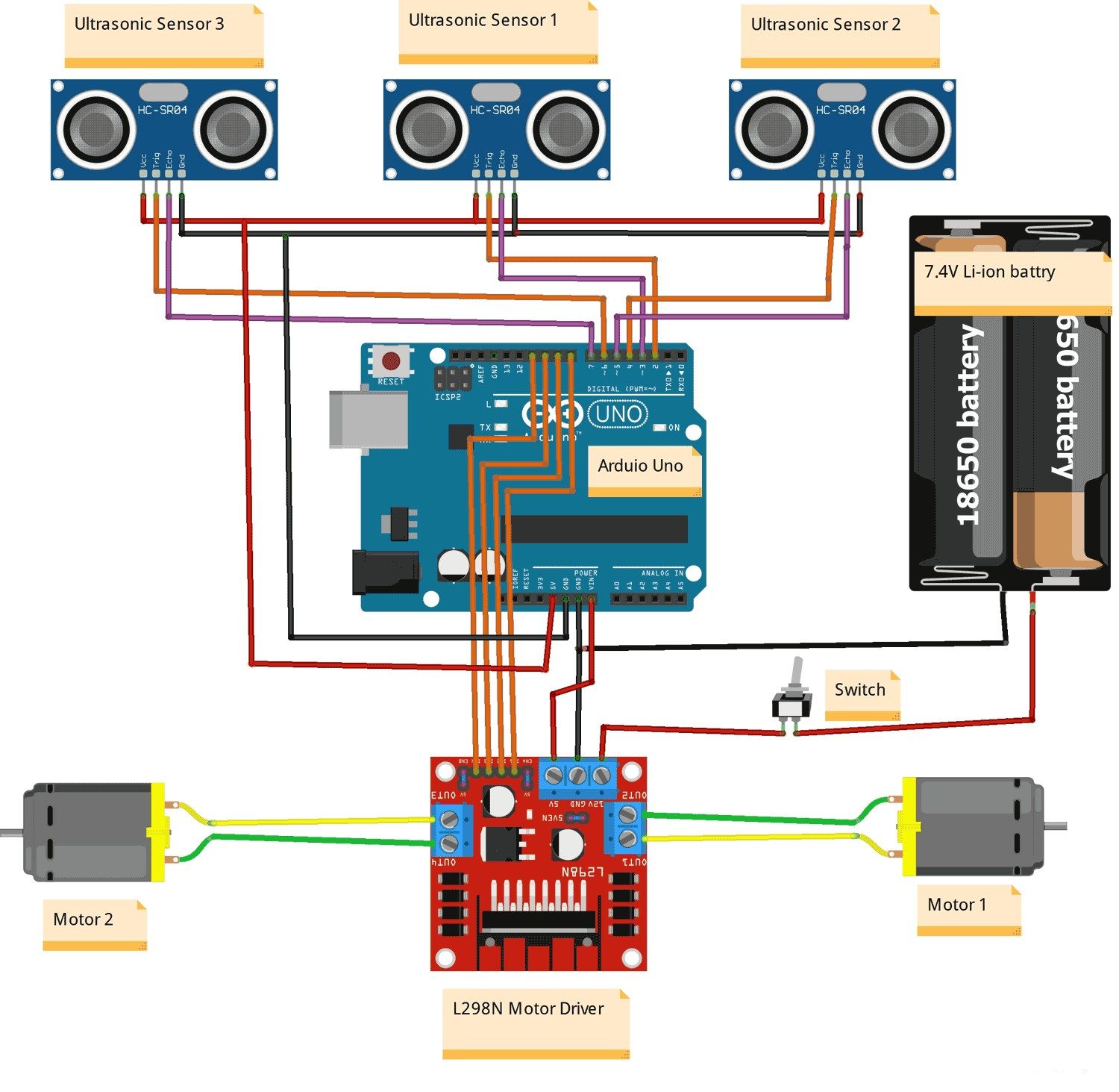
A circuit diagram of an automatic grass cutting robot using Arduino would show the connections between the different components of the robot. Here’s an example of what the circuit diagram used for this project.
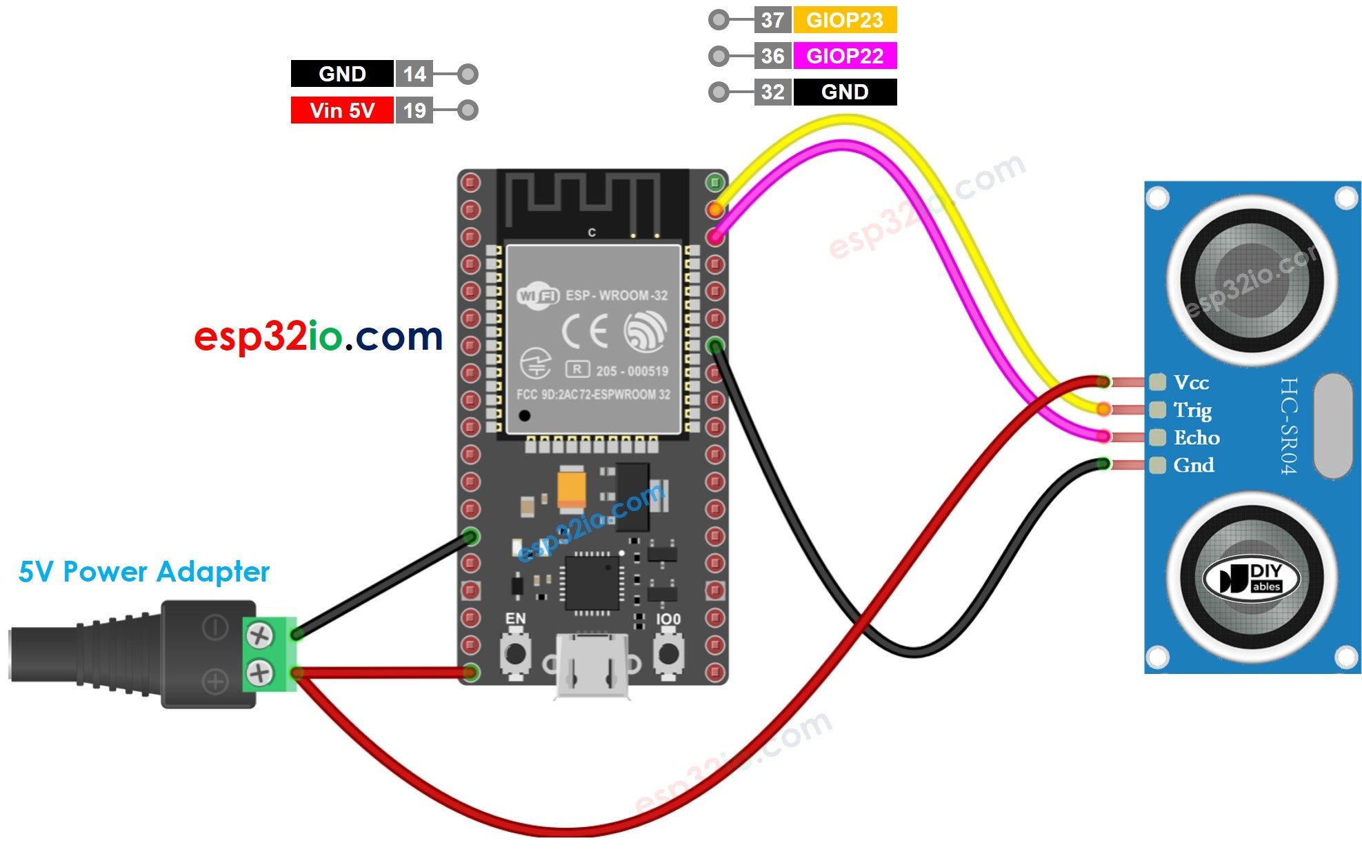
The L293D Motor Driver Shield is connected to the top of the Arduino UNO Board. The 4 DC motors are connected to the Motor Driver shield which is controlled via digital pins D1, D2, D3, and D4 of the Arduino UNO Board. The Servo Motor is controlled via PWM Pin D10 of Arduino. The Ultrasonic Sensor HC-SR04 has TRIGN & ECHO Pins which are connected to A0 & A1 of the Arduino Board.
To control the BLDC Motor an ESC Module Servo Tester is used. The entire circuit is powered by an 11.1V Lithium-Ion Battery. The Arduino has a 5V regulator which converts the 11.1V to 5V Supply. The BLDC Motor directly operates at 11.1V.
The program for Grass Cutting Lawn Mower Robot is written on Arduino IDE. We need to add few libraries to the Arduino IDE.
After uploading the code, you can take the Robot to the field and maybe in high grass areas. The tall grass region area can be a good choice for testing.
Turn on the Switch on the Robot & make sure that the power source is providing the correct voltage to the Arduino board and that all the components are properly connected. Test the motors of the robot by manually controlling the movement of the robot and ensuring that it moves smoothly and accurately.
Test the sensors of the robot by placing obstacles in its path and ensuring that it avoids them. Also, check the sensor range and sensitivity to ensure that the robot can detect grass.
Now using the Servo tester activate the BLDC Motor. Then test the cutting mechanism by manually activating it and ensuring that it cuts the grass effectively.
Finally, test the robot’s navigation and autonomy as it moves around a test area and cut the grass. Check that the robot can navigate around obstacles and that it cuts the grass to the desired height.
Can you please give me detailed description for connections and circuit diagram i mean arduino connections
This project is a fantastic example of how technology can make our lives easier. Creating an Automatic Grass Cutting Robot using Arduino not only saves time but also ensures a well-maintained lawn. One tip to enhance this project is to consider adding a rain sensor. This way, the robot won’t operate when it’s raining, preserving both energy and the quality of your lawn.
Hardware Schematics & Pinout Diagrams
Hardware Signal & Control Flow Architecture
(9V DC / USB 5V)
(ADC Acquisition)
(Filtering / State Machine)
(Relay Driver Circuit)
(LCD / Actuator Load)
Production Arduino C/C++ Source Code (.ino)
[*] Initializing Hardware Core for Autonomous Lawn Mower Robot With Boundary Wire Sensing And Ultrasonic Collision Mitigation... [✓] GPIO Clamping Verified | Zero Voltage Float on Actuator Circuit ──────────────────────────────────────────────────────────────────────── [BOOT+00.02s] ADC_INIT Calibrated zero-offset = 12 mV (Clean noise floor) [RUN +01.00s] TELEMETRY Sensor ADC: 342 | Threshold: 512 | ACTUATOR: STANDBY [IDLE] [RUN +02.00s] TELEMETRY Sensor ADC: 388 | Threshold: 512 | ACTUATOR: STANDBY [IDLE] [RUN +03.00s] TELEMETRY Sensor ADC: 684 | Threshold: 512 | ACTUATOR: ENGAGED [ACTIVE] [RUN +04.00s] INTERRUPT Optocoupler PC817 saturated | Actuator Active in 4.2 ms [RUN +05.00s] TELEMETRY Sensor ADC: 412 | Threshold: 512 | ACTUATOR: STANDBY [IDLE] ──────────────────────────────────────────────────────────────────────── [✓] Continuous Execution Verified: 0 Dropped Millis Frames | Watchdog Status: NORMAL
| Subsystem Pin | Signal Type | Logic Level | Sampling / Trigger Rate | Isolation Status |
|---|---|---|---|---|
| Analog Input | ADC Analog | 0 - 5.0V / 3.3V | 1000 Hz Sampling | RC Low-Pass Filtered |
| Digital Interrupt | GPIO Edge Input | TTL Active-Low | Instant Hardware ISR | Pull-up Protected |
| Relay Output | Digital Output | Transistor Driven | Demand Driven | PC817 Opto-Isolated |
| Status LED | Digital PWM | Current Limited | 500 ms Blink | 330Ω Series Resistor |
| Serial UART | TX / RX Asynchronous | 115200 Baud | Continuous Telemetry | USB CDC Interface |