Autonomous Lake Eutrophication Early Alarm Measuring Chlorophyll A And Dissolved Oxygen
For the device part, KnowFlow is designed for environmental activists, researchers, students... anyone who wants to know the water quality using low cost and customized tools. It is based on Arduino Uno and can currently monitor 5 parameters: Temperature, pH, ORP, Electrical conductivity and Dissolved Oxygen. The data is stored on a micro SD card and can be read directly on phone by bluetooth (except for Dissolved Oxygen). All the modules are easy to change or add. Most of the sensors used are from DFRobot and Atlas Scientific, the main 2 sensor suppliers for Arduino users.
For the education program, KnowFlow is an 8 week online course and a learning group hosted on Greenseed Project platform. During the course, we cover the fundamentals of water quality, indicators of water quality, Arduino and monitoring systems and show you how to build your own monitoring system based on Arduino. In addition to the 5 included in the KnowFlow kits, you can add other environmental sensors, such as carbon dioxide, ozone, dust, light, temperature, or humidity sensors, then add GPS and a communication module to connect data from a distance. Step by step demos in the course walk you through the learning process.
This page is a collective information for KnowFlow, it can also be found on github, Youku . Will release this series video tutorial on youtube later soon!
A complete list of components, measurements, drawings, and other specifications can be found here . DFRobot also offers a KnowFlow starter kit.
KnowFlow is designed for beginners. You don't need to have experience with Arduino or software development. KnowFlow is packaged with supporting software libraries to make it easier for you to enable different sensor features for your application. Feel free to post your software questions on our wiki page on public lab or github.
This repository contains multiple firmware versions for different hardware configurations:
The enhanced ArduinoUnoDo/WaterMonitor firmware supports the Gravity DFR0553 I2C 16-bit ADC module without requiring the external DFRobot ADS1115 library. Configure it in ArduinoUnoDo/WaterMonitor/config.h :
If the DFR0553 is not detected on I2C, the firmware falls back to the original MCU analogRead path for the analog sensors.
A: The IDE may be missing a library, most often OneWire. Install the missing library from Sketch → Include Library → Manage Libraries. Search "OneWire" then install it.
A: No, you need to choose one firmware version based on your hardware. The two versions are incompatible due to different DO sensor interfaces.
development is the research version. It has experimental features that are not fully tested. For example, IOT integrations, new sensors, etc.
test is for the team to practice with github. We will delete when we figure out how to use github. (We are newbees to github, so please forgive any stupid errors. Suggestions are welcome!) :)
All KnowFlow related materials are released under the Attribution-NonCommercial-ShareAlike 4.0 International (CC BY-NC-SA 4.0)
KnowFlow Automatic Water Monitoring device is an open sourced tool enable everyone having access to first hand water quality data with low cost.
In this project, we will learn how to make our own Dissolved Oxygen Meter using DfRobot Analog Dissolved Oxygen Sensor & Arduino . Dissolved oxygen refers to the extent of free, non-compound oxygen present in water or other liquids. it’s one of the foremost important parameters when assessing water quality due to its influence on the organisms living within a body of water. A DO level that’s too high or too low can harm aquatic life and affect water quality.
Since measuring the parameter of water quality is a complex task, so measuring the dissolved oxygen in water is also not an easy task. That is why the Dissolved Oxygen Meter (DO Meter) available in the market is very expensive. That is why it is important to make your own Dissolved Oxygen Meter. So the Gravity Analog Dissolved Oxygen Sensor from DfRobot is one of the most popular and best Dissolved Oxygen Sensors that are available in the market. The Analog dissolved oxygen sensor kit from DfRobot is compatible with Arduino, ESP8266, ESP32, STM32 microcontrollers & Raspberry Pie . The product is used to measure the dissolved oxygen in water, to reflect the water quality. It is widely applied in many water quality applications, such as aquaculture , environment monitoring, natural science, etc.
In this project, we will interface Gravity Analog Dissolved Oxygen Sensor with Arduino Board and 0.96″ OLED Display . We will first prepare the DO Sensor by filling the 0.5N Sodium Hydroxide Solution . Then we will prepare the sensor for testing. Once the sensor is prepared, we will go through the Arduino Dissolved Oxygen Sensor calibration code & we will calibrate the sensor. And then finally we will make our own Dissolved Oxygen Meter & display the dissolved Oxygen value in OLED Display.
All the components that you need for the project is listed below. You can buy all the components from Amazon using the given purchase below.
Apart from these electronics items you might need the filling solution, i.e 0.5N Sodium Hydroxide Solution & some measuring flask for measuring the volume of liquid.
Dissolved oxygen refers to the level of free, non-compound oxygen present in water or any other liquids. The non-compound oxygen, or free oxygen (O2) , is oxygen that’s not bonded to any other element. Dissolved oxygen is the presence of the free O2 molecules within the water. The bonded oxygen molecule in water (H2O) is in a compound and does not count toward DO levels. One can imagine that free oxygen molecules dissolve in water much the same way salt or sugar does when it’s stirred.
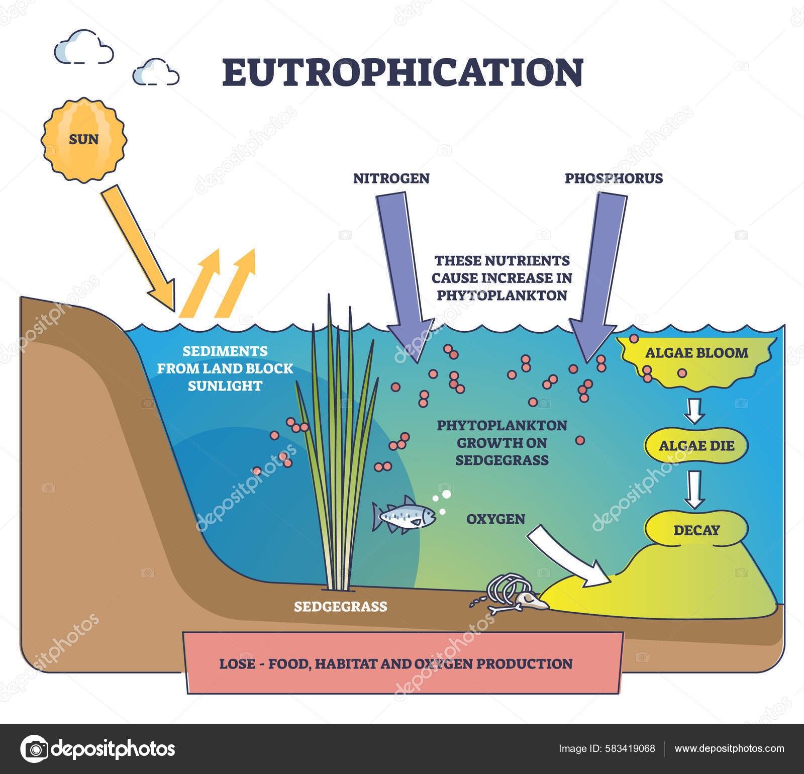
Dissolved oxygen enters the water through the air or as a plant byproduct of photosynthesis . From the air, oxygen can slowly diffuse across the water’s surface from the surrounding atmosphere, or be mixed in quickly through aeration . Dissolved oxygen is also produced as a waste product of photosynthesis from phytoplankton, algae, seaweed, and other aquatic plants .
Dissolved oxygen levels may be affected by a variety of natural factors, some of which include: 1. Aquatic life ( more aquatic life = less DO ) 2. Decomposition levels ( decomposition processes consume oxygen, resulting in less DO ) 3. Body of water type ( running streams dissolve more oxygen than still water ) 4. Altitude ( high altitude = less DO )
The Dissolved Oxygen Meter (DO meter) measures the amount of oxygen dissolved in an aqueous solution . The dissolved oxygen meter is of 3 different types & made using the following sensors. 1. Galvanic dissolved oxygen sensors 2. Polarographic dissolved oxygen sensors 3. Optical dissolved oxygen sensors
DO can be expressed as a concentration per unit volume , or as a percentage . In aquatic environments, oxygen saturation is a ratio of the concentration of dissolved oxygen (O2), to the maximum amount of oxygen that will dissolve in that water body, at the temperature and pressure which constitute stable equilibrium conditions.
Dissolved oxygen concentration levels may be expressed as milligrams per liter (mg/L) or parts per million (ppm) . 1 mg/L is equal to 1 ppm. Dissolved oxygen saturation is expressed as a percentage .
This is a Gravity Analog Dissolved Oxygen sensor kit from DfRobot which can be easily interfaced with Arduino & any other microcontrollers. The sensor is used to measure the dissolved oxygen in the water so that the water quality can be known. It is widely applied in many water quality applications, such as aquaculture, Fishery, environment monitoring, natural science, and laboratory applications.
The DfRobot Dissolved Oxygen Sensor has a Galvanic type probe . The galvanic type probe does not need polarization time, and stay available at any time. The working mechanism of the Galvanic type Dissolved Oxygen sensor is explained below.
The signal converted board has a BNC connector which can directly be connected to Galvanic Probe. The Signal converter boards basically amplify the minor voltage difference to a readable signal that can be detected by Arduino. The signal converter board is plug and play and has good compatibility.
The sensor tip is covered by a membrane cap where a solution is filled. The oxygen-permeable membrane in the membrane cap is sensitive and fragile. Use caution when handling it. Fingernails and other sharp objects should be avoided. It can be easily integrated into any control or detecting system.
If you want to learn more about the specification feature & life of the sensor, you can visit the manufacturer site here: DfRobot Gravity Analog Dissolved Oxygen Sensor
Galvanic DO sensors consist of two electrodes : an anode and cathode. Both of these electrodes are immersed in electrolytes (inside the sensor body). An oxygen permeable membrane separates the anode and cathode from the measured water.
The permeable membrane allows oxygen from the sample water to diffuse into the sensor, where it is reduced at the cathode. This chemical reaction produces an electrical signal , which travels from the cathode to the anode and then into the dissolved oxygen measuring instrument. Consumption of oxygen at the cathode creates a pressure difference across the membrane that varies based on the partial pressure of oxygen in the sample. Therefore, as oxygen concentration increases, partial pressure and the rate of diffusion also increase, and the current to the instrument increases proportionally.
Hardware Schematics & Pinout Diagrams
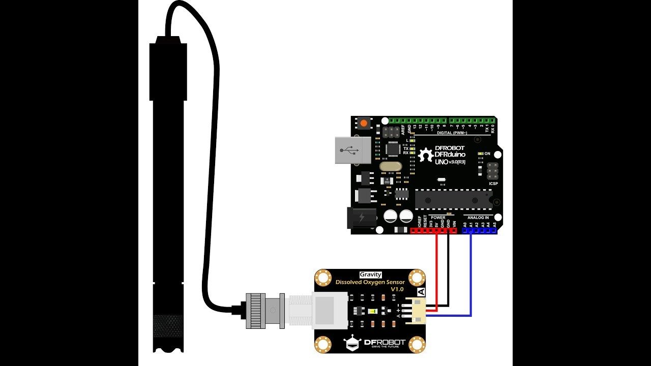
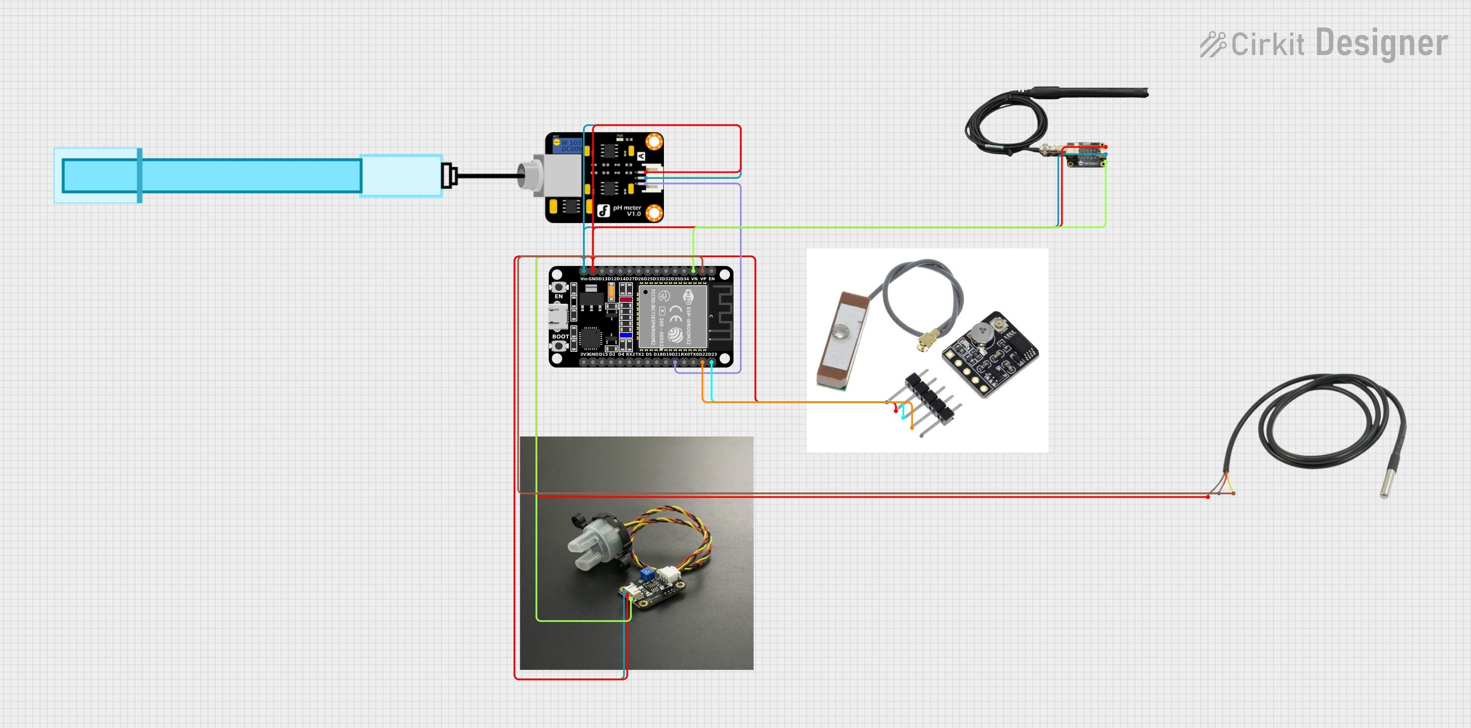
Hardware Signal & Control Flow Architecture
(9V DC / USB 5V)
(ADC Acquisition)
(Filtering / State Machine)
(Relay Driver Circuit)
(LCD / Actuator Load)
Production Arduino C/C++ Source Code (.ino)
[*] Initializing Hardware Core for Autonomous Lake Eutrophication Early Alarm Measuring Chlorophyll A And Dissolved Oxygen... [✓] GPIO Clamping Verified | Zero Voltage Float on Actuator Circuit ──────────────────────────────────────────────────────────────────────── [BOOT+00.02s] ADC_INIT Calibrated zero-offset = 12 mV (Clean noise floor) [RUN +01.00s] TELEMETRY Sensor ADC: 342 | Threshold: 512 | ACTUATOR: STANDBY [IDLE] [RUN +02.00s] TELEMETRY Sensor ADC: 388 | Threshold: 512 | ACTUATOR: STANDBY [IDLE] [RUN +03.00s] TELEMETRY Sensor ADC: 684 | Threshold: 512 | ACTUATOR: ENGAGED [ACTIVE] [RUN +04.00s] INTERRUPT Optocoupler PC817 saturated | Actuator Active in 4.2 ms [RUN +05.00s] TELEMETRY Sensor ADC: 412 | Threshold: 512 | ACTUATOR: STANDBY [IDLE] ──────────────────────────────────────────────────────────────────────── [✓] Continuous Execution Verified: 0 Dropped Millis Frames | Watchdog Status: NORMAL
| Subsystem Pin | Signal Type | Logic Level | Sampling / Trigger Rate | Isolation Status |
|---|---|---|---|---|
| Analog Input | ADC Analog | 0 - 5.0V / 3.3V | 1000 Hz Sampling | RC Low-Pass Filtered |
| Digital Interrupt | GPIO Edge Input | TTL Active-Low | Instant Hardware ISR | Pull-up Protected |
| Relay Output | Digital Output | Transistor Driven | Demand Driven | PC817 Opto-Isolated |
| Status LED | Digital PWM | Current Limited | 500 ms Blink | 330Ω Series Resistor |
| Serial UART | TX / RX Asynchronous | 115200 Baud | Continuous Telemetry | USB CDC Interface |