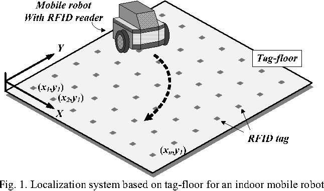
Autonomous Indoor Mobile Robot Localization Using Floor RFID Waypoint Grids And Arduino
This comprehensive Arduino RFID tutorial teaches you how to interface RFID (Radio Frequency Identification) technology with Arduino microcontrollers using the popular RC522 RFID module . Arduino RFID systems are revolutionizing DIY electronics projects , enabling makers to build professional-grade access control systems, inventory tracking solutions, and security applications. Whether you're creating an Arduino RFID door lock , attendance system, or product identification project, this guide provides complete wiring diagrams, code examples, and practical implementations to get your Arduino RFID project running successfully.
What You'll Learn: SPI communication, RFID tag reading, Arduino programming, Digital I/O control
Applications: Access control, LED toggle systems, Simple security setups, Interactive prototypes
This tutorial covers interfacing RFID with Arduino in great depth, including wiring diagrams, pinout configurations, and SPI communication setup. Learn Arduino RFID programming with hands-on code examples for reading and writing RFID tags, plus authentication protocols. Build practical Arduino RFID projects like LED control systems and access control applications. Explore real-world Arduino RFID implementations, including door locks, attendance systems , and inventory tracking solutions. Perfect for beginners and experienced makers looking to integrate RFID technology into their Arduino projects . This article was updated in May 2025 to ensure the code still works for all versions of Arduino. You can follow the same procedure for Arduino Uno , Arduino Nano, and the latest Arduino UNO R4 modules as well.
Arduino RFID technology works by using electromagnetic waves in the radio frequency spectrum for wireless communication and data transfer between RFID tags and readers. From supermarket anti-theft systems to automatic toll payment like FastTag, RFID applications are everywhere around us. With Arduino RFID projects, you can replicate these commercial applications at home - building everything from simple LED control systems to complex access control solutions. The RC522 RFID module makes Arduino RFID integration straightforward, supporting reading, writing, and authentication operations that we'll explore in this tutorial. After mastering these Arduino RFID fundamentals, you'll be ready to tackle advanced projects like our Arduino RFID door lock system.
The RFID system is comprised of two components: the RFID reader and the tags. They are also called PCD (Proximity Coupling Device) and PICC (Proximity Integrated Circuit Card). The RFID reader consists of an antenna to emit high-frequency EM waves and a reader/writer. MFRC522 from NXP is an example of such an integrated circuit. Since we are using high-frequency waves in the megahertz range, the size of the antenna can be small.
The RFID tag can be either passive or active. Active tags are powered by batteries, while the passive RFID tags are powered by energy from the reader’s interrogating EM waves. The tags are available in different forms or shapes, like cards, tags, key fobs, or stickers. Whatever the shape, the RFID tag will consist of an antenna and the RFID chip, which will store all the data. When triggered by an electromagnetic interrogation pulse from a nearby RFID reader, the tag will transmit data back to the reader. The reader will then analyze this data to identify the tag. Unlike a barcode or a QR code, the tag does not need to be within the reader’s line of sight. This makes it easier to process and can be used for tracking objects in a closed space.
The RC522 RFID module is based on the popular MFRC522 RFID reader chip from NXP. These modules are cheap and available from most online stores. MFRC522 is a highly integrated RFID reader/writer IC for contactless communication at 13.56 MHz. The MFRC522 reader supports ISO/IEC 14443 A/MIFARE and NTAG. The operating voltage of the RC522 module is 2.5V – 3.3V. Even though the maximum supply voltage is 3.3V, the communication pins are 5V tolerant. So, we can connect the module directly to an Arduino without any level shifters.
I2C interface with speed up to 400kBd in Fast mode and up to 3400kBd in High-Speed mode
The RC522 RFID module is usually supplied with a card and a key fob, both of which are MIFARE Classic tags with 1KB of storage. We can not only read these tags but can also program them with the RC522 module. Here is the picture showing the tags along with the RC522 module.
The RC522 module has a total of 8 pins. This module supports various communication protocols, and each pin has a different function for each communication protocol.
The RC522 module consists of an MFRC522 RFID chip from NXP. It is clocked at 27.12MHz by the onboard crystal oscillator in the 49S package. The board also consists of the required EMI filter circuit and matching circuit. It also consists of a PCB antenna for communicating and energizing the RFID tags.
The schematic diagram for the RC522 module is given below. The circuit consists of the bare minimum components. As we know, the main component is the MFRC522 chip. The remaining components form the EMI filter along with the matching circuit for the antenna.
While RC522 is the most popular choice for RFID Arduino projects, several alternatives exist. The PN532 NFC RFID module offers NFC compatibility for smartphone integration, making it ideal for modern Arduino RFID applications. However, RC522 remains the best choice for beginners due to its affordability, extensive library support, and 13.56MHz frequency compatibility. For high-frequency Arduino RFID projects requiring a longer range, consider UHF RFID modules, though they require more complex Arduino RFID programming.
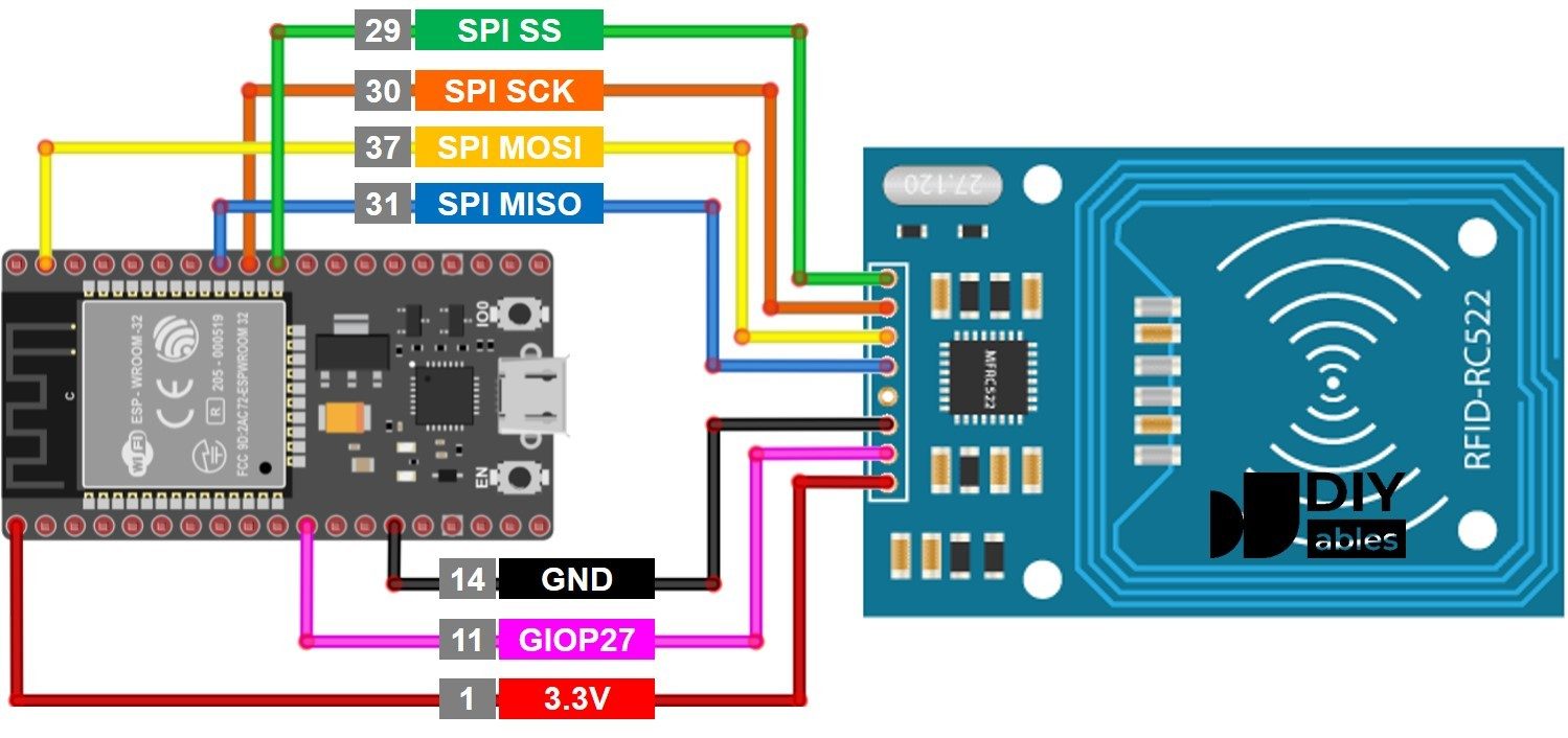
Setting up your Arduino RFID project requires proper wiring between the Arduino board and the RC522 module. For interfacing the RC522 RFID module with the Arduino , we will be using the SPI interface. Follow the circuit diagram and make the connections as per that.
The VCC and GND pins of the module are connected to the 3.3V and GND pins of the Arduino, respectively. The Reset pin is connected to the D9, and the SS, MOSI, MISO, and SCK pins are connected to the D10, D11, D12, and D13 pins of the Arduino, respectively. The SS and RST pins are configurable and can be connected to any other digital pins on the Arduino.
The Arduino code demonstrates how to read and write data to RFID tags using the RC522 module. As the connections are made, let’s look at the coding part. For that, we are going to use the MFRC522 Arduino Library by Miguel André Balboa. Since the library is not available in the Arduino library manager, download it from the MFRC522 GitHub repository and install it in the Arduino library folder. You can install it either through the Arduino IDE, by going to Sketch -> Include Library -> Add ZIP Library and selecting the downloaded ZIP file, or by simply extracting the ZIP file into the Arduino library folder.
Once the library is installed, we can test our setup with an example code. For that, open the DumpInfo example from the MFRC522 library. Here is the example code.
Once it’s compiled and uploaded to the Arduino, open the serial monitor and show any tag near the RC522 module. When the tag is in the vicinity, the reader will read all the data from the tag and will dump it into the serial monitor as shown below.
The data dump will contain all the details like Card UID, Card SAK, PICC type, and all the memory maps. The UID or Unique ID is Unique for each tag, as the name suggests. If you get a communication failed error, that’s because our serial baud rate is too slow. Increase the baud rate to 115200 in the code, and it will resolve the issue. Here in the data dump, we can see that the PICC type is MIFARE 1KB. That means the tag contains a MIFARE chip with a memory of 1KB.
Now that we have dumped the factory data from the tag, let’s see how we can write some data to the card. For that, use the following code.
Once the code is compiled and uploaded, open the serial monitor. Then scan a tag with the module. The module will write two data to the tag and will read back once it’s written. This data will then be printed to the serial monitor. See the screenshot below.
In the first lines, we have included the necessary libraries and defined the reset and SS pins. Since we are using the SPI protocol, we have included the SPI library and then the MFRC522 library for the RFID reader. The reset and SS pins can be connected to any other digital pin. The users may change it at their convenience.
Next, we have created the objects for the RFID reader library and declared the data that needs to be written. Also, declared an array to hold the data that was read from the tag.
In the setup function, we have initialized the serial communication, SPI, and the RFID reader library. We have also cleared the key array with blank data for reading and writing operations.
The function we are using to write data to the tag is the writeblock function. When this function is called, it will check if the provided block number corresponds to the data block or the trailer block. The trailer block will hold the Access Bit, which controls the read and write access to the remaining blocks. Block number 3 is the trailer block. If the provided block number does not correspond to a data block, the function will return an error message. If it’s a data block, the function will authenticate the tag with a security key and if the authentication is successful, the data will be written to the corresponding block.
Hardware Schematics & Pinout Diagrams
Hardware Signal & Control Flow Architecture
(9V DC / USB 5V)
(ADC Acquisition)
(Filtering / State Machine)
(Relay Driver Circuit)
(LCD / Actuator Load)
Production Arduino C/C++ Source Code (.ino)
[*] Initializing Hardware Core for Autonomous Indoor Mobile Robot Localization Using Floor RFID Waypoint Grids And Arduino... [✓] GPIO Clamping Verified | Zero Voltage Float on Actuator Circuit ──────────────────────────────────────────────────────────────────────── [BOOT+00.02s] ADC_INIT Calibrated zero-offset = 12 mV (Clean noise floor) [RUN +01.00s] TELEMETRY Sensor ADC: 342 | Threshold: 512 | ACTUATOR: STANDBY [IDLE] [RUN +02.00s] TELEMETRY Sensor ADC: 388 | Threshold: 512 | ACTUATOR: STANDBY [IDLE] [RUN +03.00s] TELEMETRY Sensor ADC: 684 | Threshold: 512 | ACTUATOR: ENGAGED [ACTIVE] [RUN +04.00s] INTERRUPT Optocoupler PC817 saturated | Actuator Active in 4.2 ms [RUN +05.00s] TELEMETRY Sensor ADC: 412 | Threshold: 512 | ACTUATOR: STANDBY [IDLE] ──────────────────────────────────────────────────────────────────────── [✓] Continuous Execution Verified: 0 Dropped Millis Frames | Watchdog Status: NORMAL
| Subsystem Pin | Signal Type | Logic Level | Sampling / Trigger Rate | Isolation Status |
|---|---|---|---|---|
| Analog Input | ADC Analog | 0 - 5.0V / 3.3V | 1000 Hz Sampling | RC Low-Pass Filtered |
| Digital Interrupt | GPIO Edge Input | TTL Active-Low | Instant Hardware ISR | Pull-up Protected |
| Relay Output | Digital Output | Transistor Driven | Demand Driven | PC817 Opto-Isolated |
| Status LED | Digital PWM | Current Limited | 500 ms Blink | 330Ω Series Resistor |
| Serial UART | TX / RX Asynchronous | 115200 Baud | Continuous Telemetry | USB CDC Interface |