Automated Toll Collection Prototype Using Ultra High Frequency Uhf Passive RFID And Arduino
In this project, we will introduce you to the Automatic Smart Toll Tax Collection System designed using RFID Module and Arduino . Nowadays there is a huge rush in toll plazas for paying the toll tax . Therefore, in order to reduce traffic and save time, an automatic toll collector can be used. The aim of the project is to automatically identify the RFID tag in a vehicle and to display the particular amount the user has to pay in order to pass the toll. If the user pays the amount, he can pass the gate else he will be blocked.
This project is a demo of a Smart Toll Tax Collection System . Consider there are n numbers of vehicles at Toll Plaza. When these vehicles cross the IR Sensor , the gate will be closed. At the same time, the LCD will display to put the Card to the reader for scanning. Then you can put your card on RFID and pay your bill. When the bill is successfully paid, then you can go towards the 2nd Gate. When a vehicle crosses the 2nd IR Sensor, the gate will be opened and you can go. In case the card doesn’t have a balance, you can recharge the card using this RFID and Keypad by entering the amount.
Thus this RFID Based Toll Tax Collection System can be used for Industrial applications or College Final Year projects. You can check some recent projects based on RFID & Arduino systems:
The RFID reader checks for valid, invalid, or low balances. If invalid and low balance the LCD Screen will show insufficient balance. The RFID Card can be loaded to balance using the Keypad System. When the Card is recharged, the user becomes eligible for paying and going through the toll gate.
The toll gate is fitted to the Servo Motor where the spindle of the motor rotates in a fixed angle step. When the user swipes the card the reader sends the signal to the controller and the controller checks for a valid user. If the card is valid then the controller sends a signal to the Servo motor to rotate in an anticlockwise direction so the gate opens. Some delay function is added so that the gate remains open until the vehicle moves after some time delay the controller passes the signal to rotate the Servo motor in a clockwise direction to close the gate.
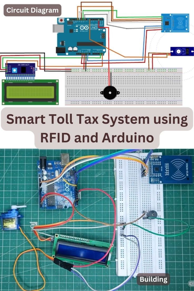
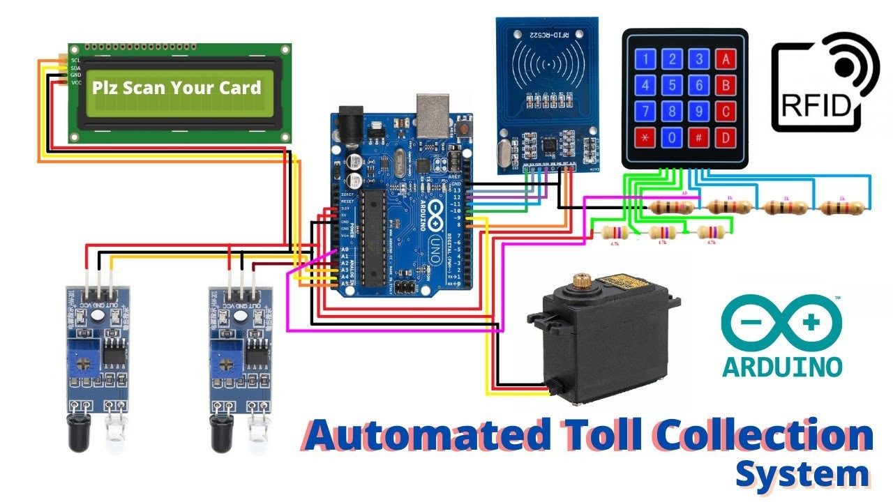
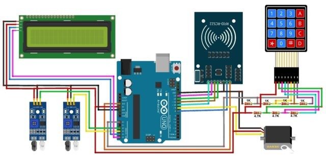
The circuit for RFID Based Toll Tax Collection System is given below. The circuit is based on the above flowchart with the use of necessary electronic components.
The RFID RC522 is an SPI Module. Therefore Connect the RFID SPI Pin to Arduino as follows.
The 16×2 LCD Display is an I2C Module. Therefore Connect the I2C LCD Pin to Arduino as follows.
The 4×4 Keypad Matrix has a total of 8 Pins. Hence it requires 8 digital Pin of Arduino for connection. In order to minimize the pin from 8 to 1, we will utilize a single analog pin. Using an array of resistors a voltage divider network can be formed so that whenever a button is pressed a different analog voltage is taken as an input.
We have a Servo Motor MG995 which is controlled using PWM Digital Pin 9 of Arduino.
Similarly we used a Pair of Infrared Proximity Switch – E18-D80NK to detect motion of a moving car travelling across the gate.
Connect the VCC & GND of both the IR Proximity Sensor to the 5V & GND of Arduino. Similarly, connect their output pin A2 & A3 of the Arduino Board.
The Mechanical Arrangement if the project looks something like shown in the image above. Thus the hardware setup for the Automated Toll Collection System using RFID & Arduino is ready for testing.
If you don’t want to assemble the circuit on a breadboard and you want PCB for the project, then here is the PCB for you. I used EasyEDA to design the Schematic & PCB. The Schematic & PCB Board for RFID Toll Collection System using Arduino looks something like the below.
The Gerber File for the PCB is given below. You can simply download the Gerber File and order the PCB from ALLPCB at 1$ only.
You can use this Gerber file to order high quality PCB for this project. To do that visit the ALLPCB official website by clicking here: https://www.allpcb.com/ .
You can now upload the Gerber File by choosing the Quote Now option. From these options, you can choose the Material Type, Dimensions, Quantity, Thickness, Solder Mask Color and other required parameters.
After filling all details, select your country and shipping method. Finally you can place the order.
The complete code for the Automated Toll Collection System using RFID & Arduino is given below. The code requires some libraries. Download the zip library from the following link below and add to to the Arduino IDE using the Library manager. 1. RC522 Library : 2. One Wire Keypad Library : 3. Liquid Crystal I2C Library :
In the following code, make changes to the balance, that you want to assign for the RFID Cards.
Make changes to the RFID Tag number as every RFID Card has its own tag number. Change all the lines with the RFID tag number that looks like this.
After uploading the code to the Arduino Board, you can start testing the project. Initially, it will display the Welcome Message.
Now when the Vehicle crosses the first IR Sensor, it will display a Vehicle Detected message. Then the system will ask you to scan the RFID Card so that you can go ahead.
Now you can scan the RFID Card for your Vehicle. The system will deduct 500 from the balance on your RFID Card. The LCD will display Bill Successfully paid message.
The amount of balance remaining in your RFID Card will be shown by the LCD Display at the same time.
Now your bill is paid. So, you can go ahead now. The the LCD will display a Safe journey Message and this is how the Automated Toll Collection System using RFID & Arduino works.
You can repeat the same process again with another RFID. Consider the RFID has only a 200 balance and the amount that is need to be paid is 500. In this case, if you scan the card, the LCD Display will show Insufficient Balance.
Therefore you need to recharge the RFID Card and load some balance. To do that press the ‘A’ Button on Keypad. The System will now go into recharging mode.
Now you can enter the amount you need to load into your RFID Card. For example, after entering 2000 from the Keypad, you can press ‘D’ to confirm. Now your card will have a 2000 balance added to the previous balance.
Thus this is how the entire system works and you can use this system to repeat the process again and again.
good day please how can i modify the code so that i can type the amount to be deducted from the rfid card instead of automatic deduction
An Arduino-based automatic toll collection prototype that uses RFID card authentication, IR sensors, a servo-controlled gate, keypad-based recharge, buzzer alerts, and an LCD display to simulate a smart toll booth system.
This project is designed to reduce manual toll booth work by automating vehicle detection, card verification, payment deduction, and gate control. When a vehicle reaches the toll point, the system asks the user to scan an RFID card. If the card is valid and has enough balance, the toll amount is deducted and the gate opens. If the balance is insufficient or the card is unknown, the system denies access and shows the proper message on the LCD.
This project is for academic and learning purposes. You can modify and improve it based on your requirements.
Hands-free toll gate using Arduino, RFID & IR sensors, detects vehicles, verifies payment, opens gate, and resets automatically for next use
This Automatic Toll Gate System Project Using Arduino demonstrates how to build a fully automated toll gate system using an Arduino Uno , RFID technology , IR sensors , and a servo motor to handle vehicle detection, payment processing, and gate control — all without manual intervention. It’s a hands-on, beginner-friendly project that mimics real-world toll operations and introduces you to integrating sensors, actuators, and identification systems with microcontrollers.
This workflow simulates a real toll booth where vehicles are automatically served as they arrive, reducing congestion and human effort.
Wiring the components correctly ensures reliable detection, authentication, and actuation.
This structure teaches how to handle real-time inputs and outputs with a microcontroller.
Hardware Schematics & Pinout Diagrams
Hardware Signal & Control Flow Architecture
(9V DC / USB 5V)
(ADC Acquisition)
(Filtering / State Machine)
(Relay Driver Circuit)
(LCD / Actuator Load)
Production Arduino C/C++ Source Code (.ino)
[*] Initializing Hardware Core for Automated Toll Collection Prototype Using Ultra High Frequency Uhf Passive RFID And Arduino... [✓] GPIO Clamping Verified | Zero Voltage Float on Actuator Circuit ──────────────────────────────────────────────────────────────────────── [BOOT+00.02s] ADC_INIT Calibrated zero-offset = 12 mV (Clean noise floor) [RUN +01.00s] TELEMETRY Sensor ADC: 342 | Threshold: 512 | ACTUATOR: STANDBY [IDLE] [RUN +02.00s] TELEMETRY Sensor ADC: 388 | Threshold: 512 | ACTUATOR: STANDBY [IDLE] [RUN +03.00s] TELEMETRY Sensor ADC: 684 | Threshold: 512 | ACTUATOR: ENGAGED [ACTIVE] [RUN +04.00s] INTERRUPT Optocoupler PC817 saturated | Actuator Active in 4.2 ms [RUN +05.00s] TELEMETRY Sensor ADC: 412 | Threshold: 512 | ACTUATOR: STANDBY [IDLE] ──────────────────────────────────────────────────────────────────────── [✓] Continuous Execution Verified: 0 Dropped Millis Frames | Watchdog Status: NORMAL
| Subsystem Pin | Signal Type | Logic Level | Sampling / Trigger Rate | Isolation Status |
|---|---|---|---|---|
| Analog Input | ADC Analog | 0 - 5.0V / 3.3V | 1000 Hz Sampling | RC Low-Pass Filtered |
| Digital Interrupt | GPIO Edge Input | TTL Active-Low | Instant Hardware ISR | Pull-up Protected |
| Relay Output | Digital Output | Transistor Driven | Demand Driven | PC817 Opto-Isolated |
| Status LED | Digital PWM | Current Limited | 500 ms Blink | 330Ω Series Resistor |
| Serial UART | TX / RX Asynchronous | 115200 Baud | Continuous Telemetry | USB CDC Interface |