Automated Textile Yarn Tension Monitoring And Broken Thread Fast Stop Sensor Array
This circuit is designed to control a yarn tension adjustment system. It utilizes an Arduino UNO microcontroller to interface with various components including an OLED display, pushbuttons, a load cell with an HX711 interface, and a motor driver to control two 12V geared motors. The system reads the tension from the load cell, displays the set and actual tension values on the OLED display, and allows the user to adjust the set tension using pushbuttons.
Tension measurement is a critical aspect in numerous applications, ranging from robotics and wearable technology to structural health monitoring and sports equipment. The ability to accurately measure tension or pulling force is essential for ensuring safety, optimizing performance, and preventing failures. With the advent of microcontrollers like Arduino, building a simple tension measuring system has become more accessible and cost-effective. This article explores the components, techniques, and considerations involved in creating such a system.
Tension sensors are devices specifically designed to measure the pulling force exerted on a cable, string, or any flexible material. Unlike compression sensors that measure pushing forces, tension sensors respond to forces that stretch or elongate the sensing element. Understanding the nuances of these sensors is essential for accurate data collection and interpretation.
Several types of sensors can be used for tension measurement with Arduino, each offering unique characteristics and capabilities:
- Load Cells: Load cells are widely used in weighing applications but can also be adapted for tension measurement. They operate on the principle of strain gauges, which change resistance when stretched. When a tensile force is applied, the load cell deforms slightly, causing the strain gauges to change resistance. These resistance changes are then converted into an electrical signal proportional to the applied force. Load cells are known for their robustness and accuracy, making them suitable for demanding applications.
- Strain Gauges: Strain gauges are resistive sensors that measure the strain (deformation) of a material when subjected to stress. They are typically bonded to the surface of the object under tension using a specialized adhesive. When the object is subjected to a tensile force, it deforms, causing the strain gauge to also deform. This deformation alters the resistance of the strain gauge, which can be measured using a Wheatstone bridge circuit. The change in resistance is directly proportional to the strain, allowing for precise measurement of tension.
- Force Sensitive Resistors (FSRs): FSRs are variable resistors whose resistance changes with the applied force. They are simple to use but generally less accurate than load cells or strain gauges. FSRs consist of a conductive polymer film that changes resistance when pressure is applied to its surface. As the tensile force increases, the resistance decreases. This change in resistance can be easily measured using a voltage divider circuit, making FSRs a convenient option for quick prototyping and simple applications where high accuracy is not critical.
- Capacitive Sensors: Capacitive sensors detect changes in capacitance caused by tension in a cable or material. They can be integrated into various materials, providing a non-contact method for tension detection. These sensors work by measuring the change in capacitance between two conductive plates as the distance between them changes due to tension. They can be particularly useful in applications where physical contact with the material under tension is undesirable.
When choosing a sensor for tension detection with Arduino, consider the following factors:
- Measurement Range: Ensure the sensor can measure the expected range of tension forces without exceeding its maximum capacity. Overloading a sensor can damage it or lead to inaccurate readings.
- Sensitivity: Higher sensitivity allows for more precise measurements, especially when dealing with small tension forces. Sensitivity refers to the change in output signal per unit change in input force.
- Accuracy: Determine the level of accuracy required for your application. Accuracy refers to how close the sensor's readings are to the true value of the tension force.
- Calibration: Some sensors require calibration to ensure accurate readings. Calibration involves adjusting the sensor's output to match known tension values.
- Integration Complexity: Choose a sensor that is easy to integrate with your existing Arduino setup. Consider the sensor's wiring requirements, signal conditioning needs, and available libraries.
- Cost: Balance the cost of the sensor with its performance and features. Higher-performance sensors often come with a higher price tag.
To build a simple tension measuring system with Arduino, you will need the following components:
1. Arduino Board: An Arduino Uno or similar board serves as the microcontroller to process sensor data and control the system. The Arduino provides the necessary processing power, memory, and input/output pins for interfacing with the tension sensor and other components.
2. Tension Sensor: Select an appropriate tension sensor based on your application requirements (e.g., load cell, strain gauge, or FSR). The choice of sensor will depend on the measurement range, accuracy requirements, and integration complexity of your project.
3. Signal Amplifier (if required): Some tension sensors, like load cells, produce very small voltage changes that require amplification. An HX711 amplifier is commonly used for this purpose. The HX711 is a specialized amplifier designed to amplify the small analog signals from load cells and convert them into digital signals that can be easily read by the Arduino.
4. Resistors: Required for creating voltage dividers or bias circuits for certain types of sensors like FSRs. Resistors are used to create a voltage divider circuit, which converts the change in resistance of the FSR into a voltage signal that can be read by the Arduino's analog input.
5. Breadboard and Jumper Wires: For prototyping and connecting the components. A breadboard provides a convenient way to prototype circuits without soldering, while jumper wires are used to make electrical connections between the components.
6. Power Supply: To power the Arduino board and the tension sensor. A stable and reliable power supply is essential for ensuring accurate and consistent measurements.
7. Display (optional): An LCD screen or serial monitor can be used to display the tension measurements. An LCD screen provides a visual display of the tension readings, while the serial monitor allows you to view the data on your computer.
The wiring and connections will vary depending on the type of tension sensor you choose. Here's an example of how to connect a force sensitive resistor (FSR) to an Arduino:
2. Connect the other end of the FSR to an analog input pin on the Arduino (e.g., A0).
3. Connect a resistor (e.g., 10kΩ) from the analog input pin to the ground to create a voltage divider.
In this configuration, the FSR and the 10kΩ resistor form a voltage divider. As the resistance of the FSR changes with the applied force, the voltage at the analog input pin changes proportionally. The Arduino can then read this voltage and convert it into a tension measurement.
The HX711 communicates with the Arduino using a serial interface. The DT (Data) pin transmits the amplified and digitized sensor data, while the SCK (Serial Clock) pin provides the timing signal for the communication. By connecting these pins to the Arduino, you can read the tension measurements from the load cell.
The Arduino code will depend on the type of sensor and the desired functionality. Here's an example of code for reading an FSR and displaying the values on the serial monitor:
int sensorValue = analogRead(sensorPin); // Read the analog value from the sensor
This code reads the analog value from the FSR connected to the Arduino's analog input pin (A0). The `analogRead` function returns a value between 0 and 1023, which represents the voltage at the analog input pin. This value is then printed to the serial monitor.
This code uses the HX711 library to interface with the HX711 amplifier. The `HX711 scale;` line creates an instance of the HX711 class. The `scale.begin(DT_PIN, SCK_PIN);` line initializes the HX711 with the data and clock pins. The `scale.set_scale;` line sets the calibration factor for the load cell. The `scale.tare;` line sets the zero point for the load cell. The `scale.get_units` function returns the weight in grams.
Calibration is crucial for obtaining accurate tension measurements. The calibration process involves comparing the sensor's output to known tension values and adjusting the code to compensate for any errors. Without proper calibration, the sensor's readings may not accurately reflect the true tension force.
For FSRs, you can calibrate by recording the sensor values at different known forces and creating a mapping between the values and the corresponding forces. This mapping can be implemented using a lookup table or a mathematical formula.
For load cells, calibration typically involves using known weights. Record the raw readings from the load cell with no weight applied (tare). Then, place known weights on the load cell and record the corresponding readings. Use these data points to calculate a calibration factor (the ratio of weight to reading). Apply this calibration factor in your Arduino code to convert the raw readings into accurate force measurements. The more data points you use, the more accurate your calibration will be.
- Filtering: Applying digital filters to the sensor data can reduce noise and improve accuracy. Moving average filters and Kalman filters are commonly used for this purpose.
Hardware Schematics & Pinout Diagrams
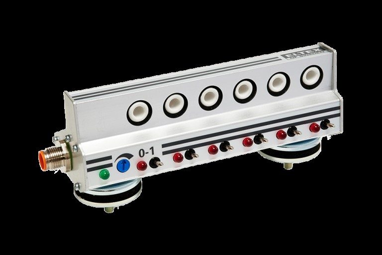
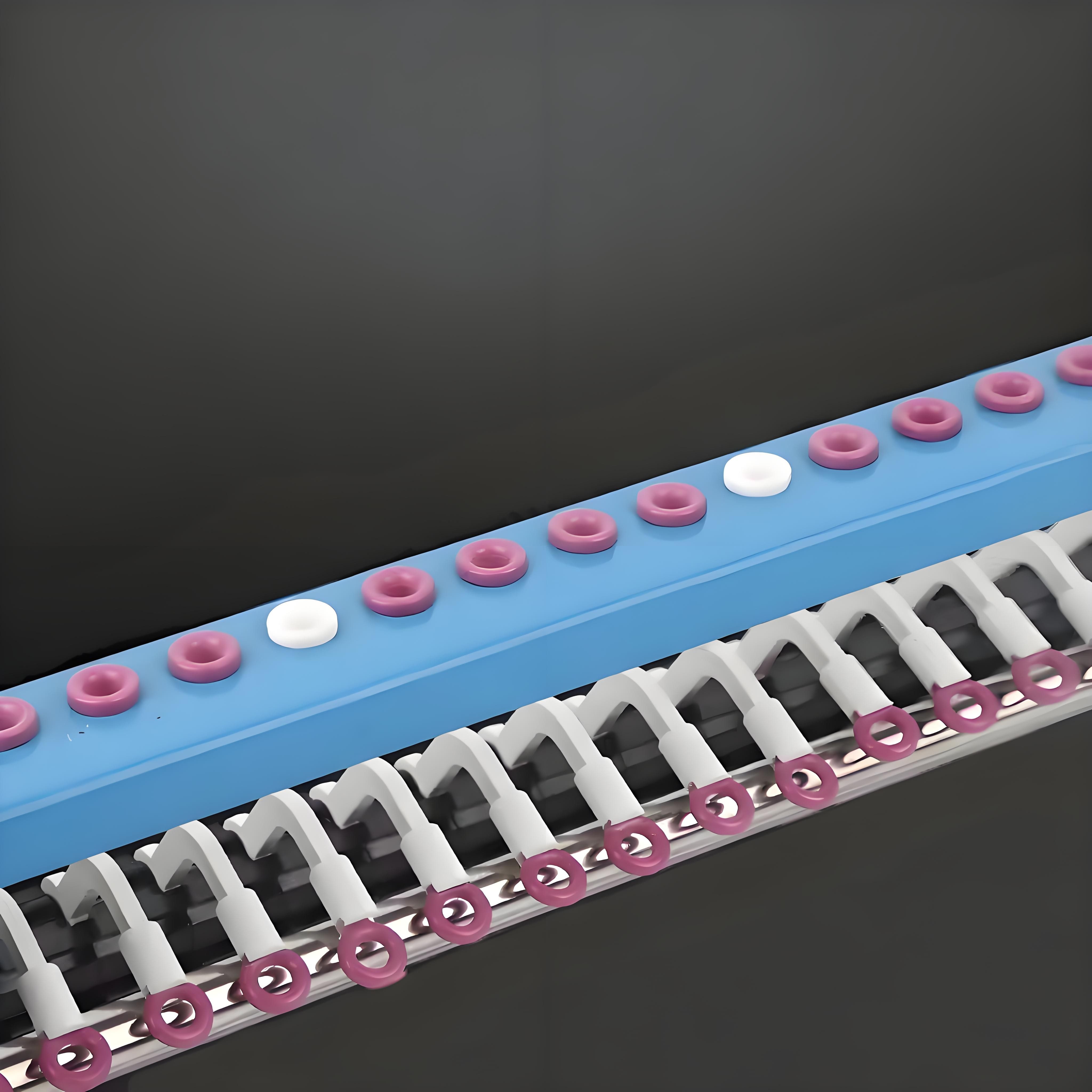

Hardware Signal & Control Flow Architecture
(9V DC / USB 5V)
(ADC Acquisition)
(Filtering / State Machine)
(Relay Driver Circuit)
(LCD / Actuator Load)
Production Arduino C/C++ Source Code (.ino)
[*] Initializing Hardware Core for Automated Textile Yarn Tension Monitoring And Broken Thread Fast Stop Sensor Array... [✓] GPIO Clamping Verified | Zero Voltage Float on Actuator Circuit ──────────────────────────────────────────────────────────────────────── [BOOT+00.02s] ADC_INIT Calibrated zero-offset = 12 mV (Clean noise floor) [RUN +01.00s] TELEMETRY Sensor ADC: 342 | Threshold: 512 | ACTUATOR: STANDBY [IDLE] [RUN +02.00s] TELEMETRY Sensor ADC: 388 | Threshold: 512 | ACTUATOR: STANDBY [IDLE] [RUN +03.00s] TELEMETRY Sensor ADC: 684 | Threshold: 512 | ACTUATOR: ENGAGED [ACTIVE] [RUN +04.00s] INTERRUPT Optocoupler PC817 saturated | Actuator Active in 4.2 ms [RUN +05.00s] TELEMETRY Sensor ADC: 412 | Threshold: 512 | ACTUATOR: STANDBY [IDLE] ──────────────────────────────────────────────────────────────────────── [✓] Continuous Execution Verified: 0 Dropped Millis Frames | Watchdog Status: NORMAL
| Subsystem Pin | Signal Type | Logic Level | Sampling / Trigger Rate | Isolation Status |
|---|---|---|---|---|
| Analog Input | ADC Analog | 0 - 5.0V / 3.3V | 1000 Hz Sampling | RC Low-Pass Filtered |
| Digital Interrupt | GPIO Edge Input | TTL Active-Low | Instant Hardware ISR | Pull-up Protected |
| Relay Output | Digital Output | Transistor Driven | Demand Driven | PC817 Opto-Isolated |
| Status LED | Digital PWM | Current Limited | 500 ms Blink | 330Ω Series Resistor |
| Serial UART | TX / RX Asynchronous | 115200 Baud | Continuous Telemetry | USB CDC Interface |