Automated Streetlight Cable Theft Detection System Using Active Loop Line Resistance Sensing
Smart Streetlight Safety System. An Arduino-based intelligent street lighting solution for public safety, road visibility automation, and energy efficiency — featuring smart sensors, GSM-based emergency alerts, and a manual emergency button.
To develop an automated street light safety system that improves public safety and road visibility while saving electrical energy using smart sensors and Arduino.
1.Arduino Uno R3:Central microcontroller for processing all sensor inputs and controlling outputs.
4.Sound Sensor:Detects loud or abnormal sounds (shouting, alarms, crashes)Active BuzzerProvides audible alert when danger or emergency is detected.
5.GSM Module (SIM900A):Sends emergency SMS alerts to authorities or contactsEmergency.
6.Push Button:Manual trigger for instant safety assistanceLED / StreetlightMain lighting output controlled by the system.
The active buzzer immediately activates to draw attention A message is printed to the Serial Monitor for real-time debugging and logging:
Hey guys, welcome back to Techatronic. You have seen the lights on the street which help in improving the clarity on roads at night. Also no
The transition towards smart cities begins with small, intelligent systems that optimize resources and increase efficiency. An automatic street light control system is a perfect example of this principle in action. By using an Arduino as the brain, we can create a device that not only conserves energy but also demonstrates the core concepts of the Internet of Things (IoT). This project is a practical introduction to automation, teaching you how to gather data from the environment and trigger a physical response.
The system's logic is beautifully simple. A light sensor, known as an LDR, acts as the system's "eye, " constantly measuring the ambient light. When the sensor detects darkness falling below a specific threshold, the Arduino commands an LED to turn on. At dawn, when the light level rises again, the system automatically switches the light off. This eliminates human intervention and wasted electricity.
Arduino Uno R3: The project's microcontroller brain. It reads inputs, processes data based on your code, and controls the output. Its 6 analog input pins are crucial for reading the light sensor's precise value.
LDR (Light Dependent Resistor): This is the key sensor. Its electrical resistance varies with light intensity; high in darkness, low in brightness. This property allows it to detect day and night cycles.
10kΩ Resistor: Used to create a "voltage divider" circuit with the LDR. This converts the LDR's variable resistance into a variable voltage that the Arduino's analog pin can read.
220Ω Resistor: A current-limiting resistor. It protects the LED from burning out by restricting the amount of current flowing from the Arduino pin.
LED (5mm): Acts as our miniature street light. It is the output device that is controlled by the Arduino's command.
Breadboard & Jumper Wires: These provide the platform and connections for building the circuit without soldering, making prototyping and modifications easy.
The code, or "sketch, " is what transforms a simple circuit into an intelligent system. It is written in the Arduino Integrated Development Environment (IDE).
In the setup function, we define the LED pin as an OUTPUT and start serial communication for monitoring.
The loop function runs continuously. It first reads the analog value from the LDR sensor (pin A0). This value ranges from 0 (dark) to 1023 (bright).
If the sensor reading is below a set threshold (e.g., 500, which you can adjust), it means it's dark. The Arduino sets the LED pin to HIGH , turning the light ON.
Else (meaning the reading is above the threshold), it sets the LED pin to LOW , turning the light OFF.
By building this circuit and uploading this code, you create a miniature smart city component. You can
Hi, project makers in this post we will see how to make Automatic Smart Street Light Using Arduino.
I have given a complete project report along with a smart street light circuit and Arduino codes for the automatic street light project.
If you are seeking award winning Arduino project you should definitely try making this useful project.
You are traveling on a highway at night time and you see that the street lights switch on and off, You may think the lights are defective!
No, it’s not about the streetlights, its all about the motion sensors that sense the motion of object.
This happens in 2 ways one is when there is dark automatically the light switches to on
The main advantage is saving power, this technology saves a lot of power which in other ways will be a waste.
Imagine the street light turned on the whole night without even a single vehicle moving on the road
In another way, if it’s automatic the light will remain on the whole day, and both cases cause extreme waste of electricity.
When IR Sensor Module detects obstacle it sends a command to Arduino to activate the LED.
This simple mechanism is put as a model which in overall context is similar to a real project.
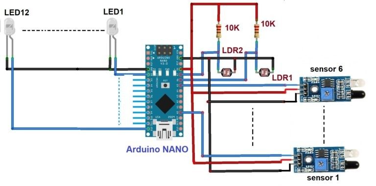
In the below circuit, you can see I will use Arduino Nano which is connected to a small breadboard.
The count of LEDs that I’m using is 8 You can choose the number of LEDs depending on your project.
In the real model, I will use the parallel type of connection to join all the LEDs.
If you have the connections made as per the circuit the project should work without any issue.
From the above visuals pointing to image 2 you can see that I have kept my hand on LDR.
I could not capture the image when I kept this model in a dark room, So this is the demo showing the working.
You can make the street light models in many ways, I chose this method since I had popsicle sticks.
Later with scissors, I cut the marked area, I made the same with the other 7 sticks.
I rolled this wire to the legs of the LED, Then I inserted these LEDs into my 3D-printed holder.
As I said earlier this is optional, you can make a street light model according to your taste if not follow this.
Now I have placed these 8 street light models on the cardboard, I used hot glue to stick them.
The series method of connection does not work here, so we will use the parallel method connection.
I soldered the wires and trimmed off the excess wire to make the model look tidy.
End of this step we will have only 2wires coming out of the 8 street light model.
Now add the Arduino and breadboard to the cardboard and finish adding the IR sensor.
Power the board with USB power supply, keep your hand i front of the IR sensor and now the LED should glow from all 8 street lights.
Also, try switching off the room light, and in no time your LED should be glowing, Thanks to the LDR.
If you have a small radio-controlled car this model becomes super creative, I have used a solar car check the results in the video below.
This is the image of our Arduino smart street light working model, you can make changes as you wish.
If you have any questions about building this project you can reach out via comments.
All the step-by-step instructions and a working video of Automatic Smart Street Light Using Arduino is given for better understanding don’t miss to check it out.
In this article we will learn how to make Automatic Street Light control using Arduino project.
An Automatic Street Light Control project using Arduino involves creating a system that automatically turns street lights on or off based on the amount of ambient light.
In this project, we’ll design an automatic, energy-efficient streetlight system using Arduino. A streetlight will automatically turn on when the outside ambient light falls below a certain threshold, as evening turns to night. They turn off when sufficient light returns in the morning to conserve energy. So, these streetlights only power on when needed.
The lighting system not only turns on and off but varies in brightness. Additionally, it will turn on if it detects any movement on the road (such as a vehicle or pedestrian) using a proximity sensor. If no movement is detected, the light remains off or dim to save energy.
When an object passes by, the light turns on in a sequence, turning brightest when the object is close and dimming as it moves away. For this demonstration project, we’ll use a series of IR proximity sensors to detect movement and a bright (high-intensity) white LED as the streetlight. Let’s get started.
Figure 1. A block diagram of the automatic street light system using Arduino, IR sensors, and LED’s.
Hardware Schematics & Pinout Diagrams
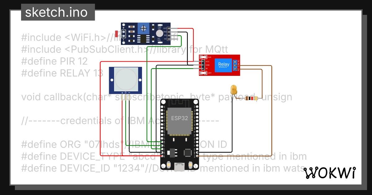

Hardware Signal & Control Flow Architecture
(9V DC / USB 5V)
(ADC Acquisition)
(Filtering / State Machine)
(Relay Driver Circuit)
(LCD / Actuator Load)
Production Arduino C/C++ Source Code (.ino)
[*] Initializing Hardware Core for Automated Streetlight Cable Theft Detection System Using Active Loop Line Resistance Sensing... [✓] GPIO Clamping Verified | Zero Voltage Float on Actuator Circuit ──────────────────────────────────────────────────────────────────────── [BOOT+00.02s] ADC_INIT Calibrated zero-offset = 12 mV (Clean noise floor) [RUN +01.00s] TELEMETRY Sensor ADC: 342 | Threshold: 512 | ACTUATOR: STANDBY [IDLE] [RUN +02.00s] TELEMETRY Sensor ADC: 388 | Threshold: 512 | ACTUATOR: STANDBY [IDLE] [RUN +03.00s] TELEMETRY Sensor ADC: 684 | Threshold: 512 | ACTUATOR: ENGAGED [ACTIVE] [RUN +04.00s] INTERRUPT Optocoupler PC817 saturated | Actuator Active in 4.2 ms [RUN +05.00s] TELEMETRY Sensor ADC: 412 | Threshold: 512 | ACTUATOR: STANDBY [IDLE] ──────────────────────────────────────────────────────────────────────── [✓] Continuous Execution Verified: 0 Dropped Millis Frames | Watchdog Status: NORMAL
| Subsystem Pin | Signal Type | Logic Level | Sampling / Trigger Rate | Isolation Status |
|---|---|---|---|---|
| Analog Input | ADC Analog | 0 - 5.0V / 3.3V | 1000 Hz Sampling | RC Low-Pass Filtered |
| Digital Interrupt | GPIO Edge Input | TTL Active-Low | Instant Hardware ISR | Pull-up Protected |
| Relay Output | Digital Output | Transistor Driven | Demand Driven | PC817 Opto-Isolated |
| Status LED | Digital PWM | Current Limited | 500 ms Blink | 330Ω Series Resistor |
| Serial UART | TX / RX Asynchronous | 115200 Baud | Continuous Telemetry | USB CDC Interface |