Automated Rainwater Harvester First Flush Diverter With Turbidity Sensor Threshold Control
This project automates a rainwater harvesting setup the way it should actually be done: an ESP32 watches a rain sensor, diverts the dirty first flush to drain, checks turbidity before routing water to the storage tank, and manages tank levels with ultrasonic sensing — all with valves, a filter-status indicator and an LCD event log. It turns a plumbing chore into an instrumentation project. Suitable for B.E./B.Tech final-year projects in IoT and Embedded Systems.
Rainwater harvesting fails in practice for boring reasons: nobody diverts the first flush, the filter clogs silently, and the tank overflows or runs dry because nobody watches it. This controller handles all three automatically. A rain sensor detects the onset of rain; a motorized ball valve first routes the first flush (design target: first few minutes or a set volume) to drain, then a turbidity sensor gates the clean flow into the storage tank — if the water stays dirty, the controller holds the drain route and logs the event. An ultrasonic sensor tracks tank level, stops inflow at full, and a second valve tops up from the mains only below a reserve level. A filter-clog proxy (flow-time vs level-rise comparison) drives a "clean filter" indicator. Every routing decision appears on the LCD and in an SD-card event log.
Analog optical sensor checks incoming water clarity against a configured threshold.
Two 5 V motorized ball valves route flow to drain or tank, driven via relay/H-bridge.
Every routing decision, turbidity reading and valve action is written to the card.
Rain detection, first-flush diversion to drain, turbidity-gated routing to the storage tank, overflow-safe level management with optional mains top-up, and a filter-clog indicator — the full harvesting loop.
An optical turbidity sensor samples the incoming flow; if clarity stays below the configured threshold after the first flush, the controller holds the drain route and logs the event. Thresholds are set during the buyer's own clear-vs-dirty water check.
No — the prototype demonstrates the complete control logic on a scaled tank model. Real rooftop plumbing is the buyer's deployment.
5 V motorized ball valves driven through relay/H-bridge outputs from the ESP32, with timed positioning and stall guard.
Scaled demo rig, buyer-calibrated turbidity thresholds, timed (not encoder) valve positioning, and the clog indicator is a proxy metric.
Yes — for IoT and Embedded Systems programs. It combines multi-sensor fusion, state-machine control, water-quality reasoning and honest calibration, all strong viva material.
This project builds a smart door lock around an ESP32 and an RC522 RFID reader: authorized RFID tags unlatch a solenoid-drive...
This project is a touchless automatic soap dispenser built on an ESP32: an IR proximity sensor detects a hand and a peristalt...
This project builds a voice-controlled home automation hub: an ESP32 drives a 4-channel relay board switching real lamps and...
The ESP32 is the highest-return component for a final-year IoT project: Wi-Fi and Bluetooth on-chip, dual-core 240 MHz, 3.3V logic, deep sleep at ~10 uA. This guide covers how it works, wiring, the mistakes that kill builds, and 7 project ideas linked to real projectech.in listings.
Turn ESP32 sensor nodes into a polished smart-home demo with Home Assistant. Covers the ESPHome YAML path vs the flexible MQTT path, entities and auto-discovery, automations that make projects feel like systems, dashboards, and deployment gotchas.
Choose ESP32 for most IoT projects because Wi-Fi and Bluetooth are built in. Choose Arduino Uno for simple sensor/control projects that do not need internet connectivity. Choose Raspberry Pi when the project needs Linux, cameras, a database, a web server, or AI. One-line rule: ESP32 for connected embedded systems, Arduino for simple control, Pi for computer-like workloads. The exceptions are mainly 5V-heavy circuits, camera/AI applications, and projects that need a full operating system.
An efficient Rainwater Collecting System with a Water Quality-Based Filtration System to promote sustainable water management practices.
This repository contains the implementation of a Rainwater Harvesting System that dynamically monitors and filters rainwater based on real-time quality metrics using sensors and an Arduino-based setup.
This project addresses water scarcity and promotes sustainable water practices by:
This project was developed by students of the Gokongwei College of Engineering, De La Salle University, under the guidance of Mr. Jay Robert Del Rosario.
Rainwater harvesting has become an essential solution for addressing water scarcity. However, the quality of harvested rainwater changes significantly during rainfall. The initial runoff, known as the first flush , contains dust, bird droppings, leaves, roof debris, and atmospheric pollutants, making it unsuitable for storage.
Traditional rainwater harvesting systems generally rely on fixed timers to divert the first flush. These methods cannot adapt to changing weather conditions, roof cleanliness, or rainfall intensity, leading to unnecessary water loss or poor-quality water storage.
This project introduces an Adaptive Sensor-Fusion-Based Rainwater Quality Classification System that continuously measures rainwater quality using multiple sensors, predicts water quality using Machine Learning, and dynamically determines the end of the contaminated first-flush period.
Based on the predicted water quality, the system automatically diverts water into the most appropriate destination using electronically controlled valves.
This project solves these problems using Machine Learning , IoT , and real-time sensor fusion .
The proposed system continuously monitors incoming rainwater using multiple water-quality sensors.
Instead of relying on a predetermined first-flush duration, the Machine Learning model evaluates the sensor readings in real time and classifies the water into different quality levels.
The controller then automatically routes the water through a multi-path pipe system to the appropriate destination.
These results indicate that the model generalizes well on the generated dataset and shows no significant signs of overfitting.
The model primarily relies on Turbidity and TDS , which are physically meaningful indicators of rainwater quality.
If you found this project interesting, consider giving it a ⭐ on GitHub. It helps others discover the project and motivates future development.
This project is released under the MIT License and is intended for educational, research, and non-commercial purposes.
Rainwater harvesting system that uses sensor fusion and machine learning to classify rainwater quality in real time, dynamically determine the end of the first-flush period, calculate a Rainwater Quality Index (RQI), and automatically divert water to the most suitable destination using an electronically controlled multi-path valve system.
In this tutorial, we’re going to be looking into this turbidity sensor released by DFrobot. We will be making a low cost water turbidity meter based on the Arduino, Turbidity Sensor, and the I2C LCD. I will cover the Analog and digital modes of the Turbidity sensor. I will also explain how to calibrate the Turbidity sensor if in case you get the wrong values.
You can also ready my article on IoT based Water level monitoring and automatic water pump control system using the ESP32 WiFi + Bluetooth Module, Waterproof Ultrasonic Sensor, and the New Blynk V2.0 more…
This mechanism is relatively simple as light will be blocked by particles suspending in the liquid.
The turbidity can be measured by detecting the amount of light going through the liquid sample.
The turbidity unit is measured in NTU “ Nephelometric Turbidity Units” which is global standard. The larger the turbidity is, the cloudy of the sample is. Turbidity sensor connects to the microcontroller through an analog to digital converter through this A to D converter.
The output signal can be switched between analog and digital. Under analog mode the signal wire from A to D converter goes to the analog input pin on the microcontroller. The turbidity is represented by the voltage of the output pin.
The larger the turbidity is, the smaller this output voltage will be. The voltage ranges from 0 to 4.5 volts. Under digital mode the signal wire from the converter goes to the digital pin of the microcontroller the sensor sends out a 5v signal when turbidity reaches a threshold value. This value can be adjusted by the on board potentiometer on the A & D converter. Turbidity sensor is often used in water quality monitoring.
*Disclosure: These are affiliate links. As an Amazon Associate I earn from qualifying purchases.
Water turbidity is an important measuring unit to determine water quality and describes the degree of water cloudiness.
Turbidity is caused by a huge number of small particles that are suspended in water and invisible to the human eye. While bigger particles are settling down rapidly, small particles – also known as colloids – are settling down very slowly or not at all.
Turbidity in rivers or lakes is often caused by human activities like construction, mining and agriculture. Storm water runoff after a rainfall can wash up sediments from urbanized areas, industries and farmland.
Hardware Schematics & Pinout Diagrams
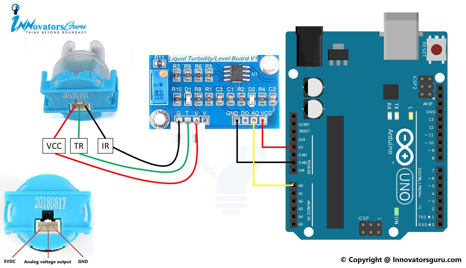
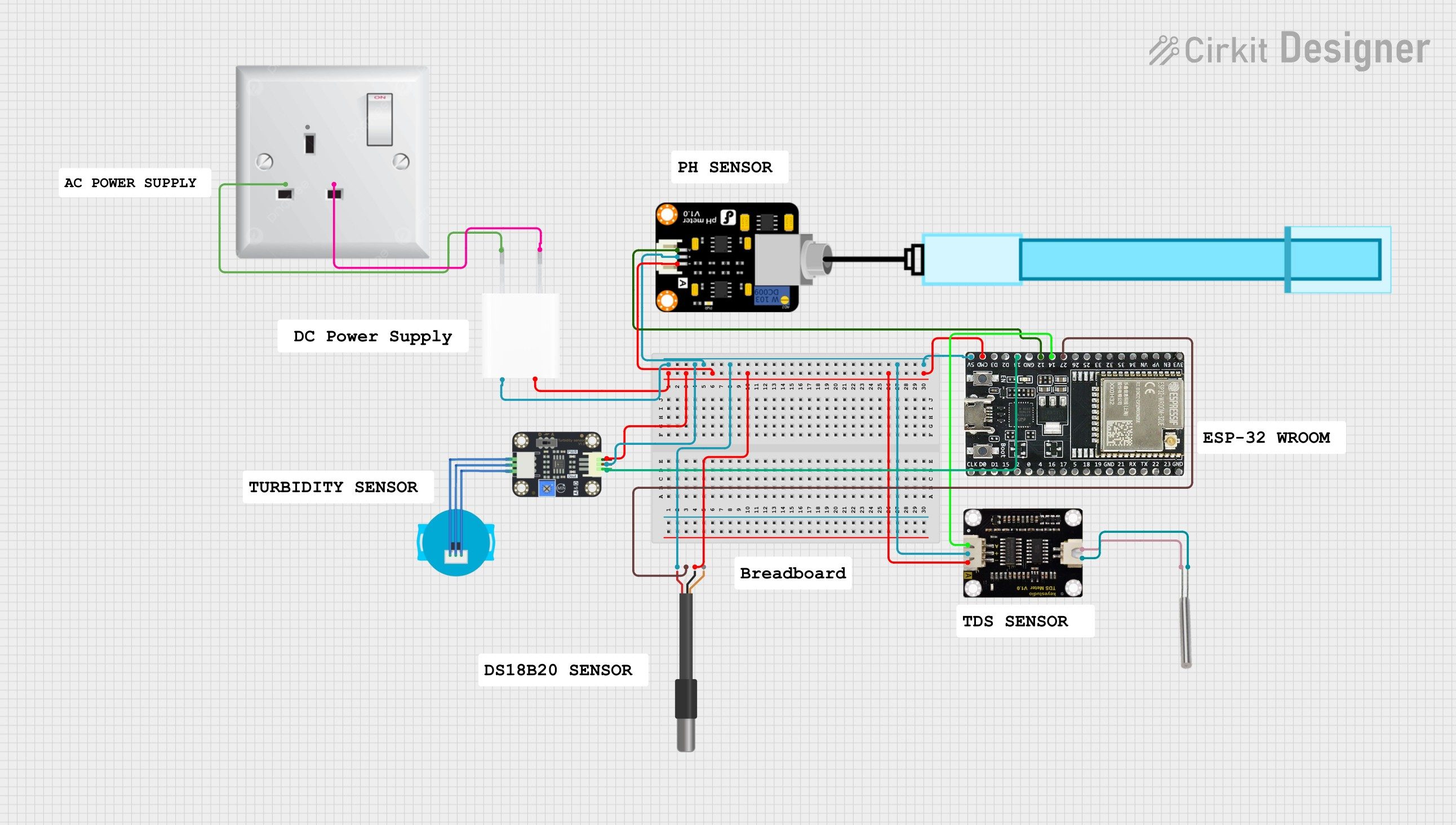
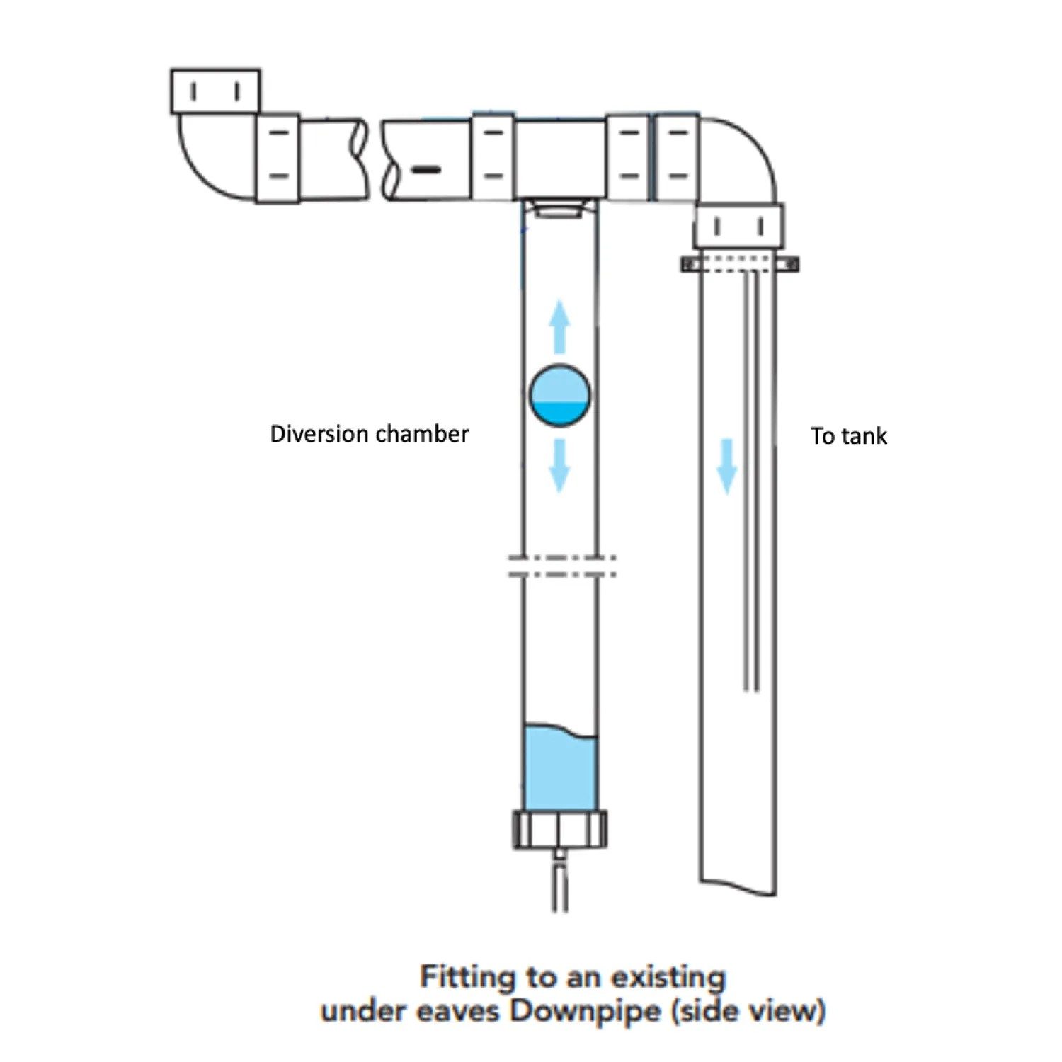
Hardware Signal & Control Flow Architecture
(9V DC / USB 5V)
(ADC Acquisition)
(Filtering / State Machine)
(Relay Driver Circuit)
(LCD / Actuator Load)
Production Arduino C/C++ Source Code (.ino)
[*] Initializing Hardware Core for Automated Rainwater Harvester First Flush Diverter With Turbidity Sensor Threshold Control... [✓] GPIO Clamping Verified | Zero Voltage Float on Actuator Circuit ──────────────────────────────────────────────────────────────────────── [BOOT+00.02s] ADC_INIT Calibrated zero-offset = 12 mV (Clean noise floor) [RUN +01.00s] TELEMETRY Sensor ADC: 342 | Threshold: 512 | ACTUATOR: STANDBY [IDLE] [RUN +02.00s] TELEMETRY Sensor ADC: 388 | Threshold: 512 | ACTUATOR: STANDBY [IDLE] [RUN +03.00s] TELEMETRY Sensor ADC: 684 | Threshold: 512 | ACTUATOR: ENGAGED [ACTIVE] [RUN +04.00s] INTERRUPT Optocoupler PC817 saturated | Actuator Active in 4.2 ms [RUN +05.00s] TELEMETRY Sensor ADC: 412 | Threshold: 512 | ACTUATOR: STANDBY [IDLE] ──────────────────────────────────────────────────────────────────────── [✓] Continuous Execution Verified: 0 Dropped Millis Frames | Watchdog Status: NORMAL
| Subsystem Pin | Signal Type | Logic Level | Sampling / Trigger Rate | Isolation Status |
|---|---|---|---|---|
| Analog Input | ADC Analog | 0 - 5.0V / 3.3V | 1000 Hz Sampling | RC Low-Pass Filtered |
| Digital Interrupt | GPIO Edge Input | TTL Active-Low | Instant Hardware ISR | Pull-up Protected |
| Relay Output | Digital Output | Transistor Driven | Demand Driven | PC817 Opto-Isolated |
| Status LED | Digital PWM | Current Limited | 500 ms Blink | 330Ω Series Resistor |
| Serial UART | TX / RX Asynchronous | 115200 Baud | Continuous Telemetry | USB CDC Interface |