Automated Railway Level Crossing Barrier Gate With Approaching Train Rf Sensor Interlock
The Automatic Railway Crossing System is an Arduino-based smart railway safety project that automatically controls railway gates, road traffic signals, warning lights, buzzer alerts, and train signals using IR sensors and servo motors.
The system detects an approaching train using an Entry IR Sensor and automatically closes the railway crossing gate. While the train passes, warning lights flash and a buzzer sounds to alert road users. Once the train reaches the Exit IR Sensor, the gates reopen and normal traffic flow resumes.
Arduino-based Automatic Railway Crossing System with IR sensor train detection, servo-controlled gates, warning lights, buzzer alerts, road traffic signals, and train signal automation.
This project builds an automatic railway level crossing gate that detects an approaching train with two IR sensor modules and closes a servo-driven gate arm on its own — with a red signal light and warning buzzer while the crossing is occupied, and automatic reopening once the train has fully cleared. Everything runs on an Arduino UNO with documented firmware, so the sensing-to-actuation chain is fully explainable in a viva. Suitable for B.E./B.Tech final-year projects in Electronics, Electronics & Telecommunication and IoT.
Level crossings remain one of the most accident-prone points on a railway network, and manually operated gates depend on a gateman noticing the train, reaching the gate in time, and closing it before road traffic enters the tracks. Human reaction time, fatigue, and unmanned crossings make this chain fragile. The engineering answer is automatic detection: sense the train's approach electronically, close the gate before it arrives, and reopen only after it has fully cleared. This project implements that exact loop at model scale — two reflective IR sensor modules watch the track on either side of the crossing, an Arduino UNO runs the detection and state-machine logic, an SG90 servo drives the gate arm, and red/green signal LEDs plus a buzzer warn road users. Because the prototype is built on a breadboard with visible wiring, every signal in the chain can be probed and explained.
A single sensor can only say "something passed". Two sensors — one on each approach — let the controller distinguish arrival from departure and keep the gate closed until the train's tail has fully cleared the crossing. It also makes the logic direction-agnostic, so trains approaching from either side are handled identically.
Yes, and this is stated openly. Reflective IR modules react to ambient infrared, so strong sunlight or halogen lamps can false-trigger them. The build is designed for indoor demonstration, and the calibration guide sets the sensitivity for the demo room. Modulated-IR sensing is listed as future scope for outdoor use.
IR obstacle modules are inexpensive, respond in milliseconds, and give a clean digital output the Arduino reads directly. Ultrasonics are slower and noisier at close range; LDRs depend on shadows and ambient light. The tradeoff is the ambient-IR sensitivity, which is owned openly in the limitations section.
No. This is a model-scale academic prototype. Real level crossings need fail-safe design, redundancy, battery backup and safety certification (SIL-rated systems) that a student build cannot claim. The project demonstrates the control principle — detect, warn, close, verify clearance — that real systems implement to railway standards.
The buyer runs a documented procedure: set each sensor's detection distance with its potentiometer for the model train, verify the debounce window, check the gate closes on arrival and reopens after the tail clears the departure sensor, then tune the servo angles and clearance delay. The report template records the student's own readings.
Yes — for Electronics, Electronics & Telecommunication and related programs. It combines sensor interfacing, embedded C firmware with a state machine, and servo actuation into one demonstrable system, with honest limitations that give the viva real depth. Suitable for B.E./B.Tech final-year projects in Electronics, Electronics & Telecommunication.
This project builds a real-time audio spectrum analyzer that splits any music or tone source into seven frequency bands using...
This project builds an automatic railway track crack detection system using IR sensors mounted on a rail-running inspection f...
This project builds a clap switch using a sound sensor module and an Arduino Uno that switches a lamp on and off with two cla...
How to measure current in a student electronics build: shunt-resistor sensing with amplification and high-side versus low-side placement, compared against isolated Hall-effect sensing, with sizing rules, calibration steps, and three practical recipes.
The LM358 is the cheapest op-amp in every student kit, and it is all you need to learn the two circuits that matter: the inverting and non-inverting amplifier (gain = resistor ratio) and the comparator (sensor threshold into a digital signal). This guide works the gain math with real resistor values, explains single-supply limitations, shows sensor signal-conditioning circuits for LDRs, thermistors and current sensing, and lists the classic wiring mistakes that make an op-amp circuit sit at the rail.
This guide lists 50+ final year project ideas for ECE (Electronics / E&TC) students, grouped by domain — IoT & embedded systems, robotics & automation, power & energy systems, communication & signal processing, plus mini-project picks — each with a one-line scope note covering the core hardware. Pick your idea based on four realities: a component budget (typical prototypes cost ₹2,000–8,000), what lab equipment you can access, a 6–8 month timeline, and whether your team can handle soldering and basic PCB work.
An automatic railway crossing gate built on an Arduino that detects approaching trains with IR sensor pairs on both approaches, closes a servo-driven barrier with flashing warning lights and a buzzer, and reopens only after the train has fully cleared. A direction-aware state machine handles trains from either side, and the design fails safe — barrier closed, alarm on — on sensor fault or power loss. Suitable for B.E./B.Tech final-year projects in Electrical and Electronics Engineering.
Level crossings are among the deadliest points on any railway network. Where roads meet tracks, safety depends on a gate closed in time, every time — yet many crossings still depend on a gateman's judgment or, at unmanned crossings, nothing at all. The failure modes are familiar: a gate opened too early, a train from the unexpected direction, a warning missed in traffic noise. Automating the crossing removes human timing error: sensors detect the approaching train on either side, the barrier closes with lights and sound, and reopens only when the train has fully cleared. Real railways use track circuits and axle counters; at model scale the same logic — direction-aware detection, a strict state machine and fail-safe defaults — can be built with an Arduino, IR sensor pairs and a servo barrier. This project is that working model, including the safety reasoning behind it.
Automatic train detection with IR sensor pairs on both approaches — covers trains coming from either direction Bidirectional logic — the system knows which sensor the train hit first and behaves correctly for both directions Servo-driven striped barrier arm with smooth close/open motion Flashing red warning LEDs + loud buzzer alarm while the train approaches and passes 16×2 LCD showing live status: IDLE, TRAIN APPROACHING, GATE CLOSED, TRAIN PASSING Automatic reopening — the gate opens only after the exit-side sensor confirms the train has fully cleared Fail-safe behavior — on sensor fault or power loss the barrier stays closed with the alarm sounding Configurable gate timing (approach distance vs barrier close speed) in firmware Manual override switch for maintenance mode during demos Toy train track model included, so the complete sequence runs without external props
Fully assembled and sequence-tested railway gate model with train track Complete firmware source code (Arduino IDE, well-commented state machine) Circuit diagram and wiring schematic Sensor alignment and timing-calibration procedure sheet Project report PDF (crossing accident background, design, timing analysis, results, conclusion) PPT presentation for final review Viva Q&A preparation document (state machines, IR sensing, servo control, fail-safe design) Demo runbook — how to run the train-pass sequence in your review
Model scale — IR beam ranges and timings are calibrated for the included track model; a real crossing would use axle counters or track circuits, which the report compares honestly. IR sensors can false-trigger in direct bright sunlight or with reflective obstacles; the demo is tuned for indoor review-hall lighting. The barrier is a light model arm — it demonstrates the mechanism, not the torque of a real gate motor. Fail-safe covers sensor fault and power loss; it does not cover deliberate vehicle intrusion under a closed barrier.
Arduino Uno (ATmega328P) with servo library control IR transmitter–receiver sensor pairs ×2 (approach + exit sides, ~15 cm detection range) SG90/MG996R servo motor driving the striped barrier arm Red flashing warning LEDs + active buzzer (alarm circuit) 16×2 LCD with I2C backpack (status display) Firmware: Arduino IDE (state machine — IDLE, APPROACHING, CLOSED, PASSING, FAULT) Toy train track model with train (demo hardware) 5 V regulated power with common ground for servo and logic
Hardware Schematics & Pinout Diagrams
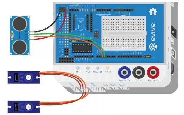
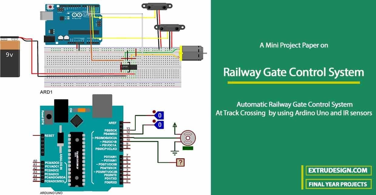
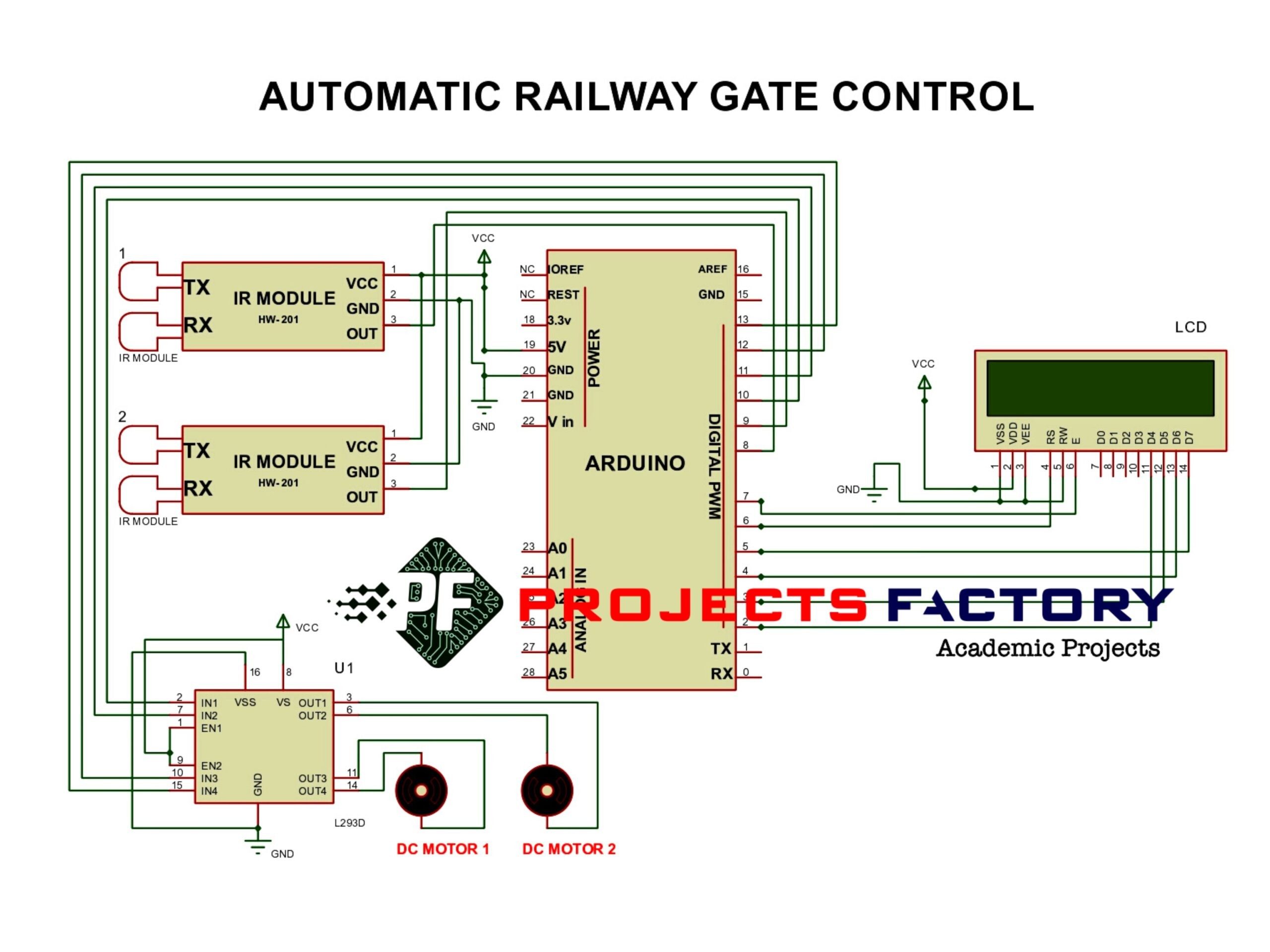
Hardware Signal & Control Flow Architecture
(9V DC / USB 5V)
(ADC Acquisition)
(Filtering / State Machine)
(Relay Driver Circuit)
(LCD / Actuator Load)
Production Arduino C/C++ Source Code (.ino)
[*] Initializing Hardware Core for Automated Railway Level Crossing Barrier Gate With Approaching Train Rf Sensor Interlock... [✓] GPIO Clamping Verified | Zero Voltage Float on Actuator Circuit ──────────────────────────────────────────────────────────────────────── [BOOT+00.02s] ADC_INIT Calibrated zero-offset = 12 mV (Clean noise floor) [RUN +01.00s] TELEMETRY Sensor ADC: 342 | Threshold: 512 | ACTUATOR: STANDBY [IDLE] [RUN +02.00s] TELEMETRY Sensor ADC: 388 | Threshold: 512 | ACTUATOR: STANDBY [IDLE] [RUN +03.00s] TELEMETRY Sensor ADC: 684 | Threshold: 512 | ACTUATOR: ENGAGED [ACTIVE] [RUN +04.00s] INTERRUPT Optocoupler PC817 saturated | Actuator Active in 4.2 ms [RUN +05.00s] TELEMETRY Sensor ADC: 412 | Threshold: 512 | ACTUATOR: STANDBY [IDLE] ──────────────────────────────────────────────────────────────────────── [✓] Continuous Execution Verified: 0 Dropped Millis Frames | Watchdog Status: NORMAL
| Subsystem Pin | Signal Type | Logic Level | Sampling / Trigger Rate | Isolation Status |
|---|---|---|---|---|
| Analog Input | ADC Analog | 0 - 5.0V / 3.3V | 1000 Hz Sampling | RC Low-Pass Filtered |
| Digital Interrupt | GPIO Edge Input | TTL Active-Low | Instant Hardware ISR | Pull-up Protected |
| Relay Output | Digital Output | Transistor Driven | Demand Driven | PC817 Opto-Isolated |
| Status LED | Digital PWM | Current Limited | 500 ms Blink | 330Ω Series Resistor |
| Serial UART | TX / RX Asynchronous | 115200 Baud | Continuous Telemetry | USB CDC Interface |