Automated Pickling Bath Acid Concentration Titration Station Using Optical Refractometry
A "simulation-to-reality" framework for intelligent pH control in complex buffered systems using low-cost hardware, physics-informed neural networks, and Bayesian active learning.
This project presents an intelligent, low-cost automated titration platform designed for rapid and precise pH regulation in complex buffered systems. Unlike traditional PID or black-box ML approaches, our system embeds physicochemical priors into a transferable neural surrogate model, and uses Gaussian-process-based active learning to close the loop between simulation and experiment.
The platform autonomously determines optimal titrant additions, corrects for model-reality mismatches, and converges to target pH values in as few as 3–4 iterations, without requiring historical experimental data.
Theoretical Prior Generation Solve charge balance equations numerically to generate titration curves for diverse buffer systems → train physics-informed surrogate model.
Transfer Learning to Real System Load pretrained model → fine-tune with real-time experimental data via Gaussian Process residual modeling.
Active Learning Loop Use target-directed EI to select next titrant volume → execute via Arduino → update model → iterate until |pH − target| < 0.1.
SDL-python/ ├─ main.py # Tkinter-based pH control UI ├─ data_collection.py # CLI data recorder for titration curves ├─ to_arduino.py # Serial protocol helper for pumps/sensors ├─ activate_learn/ # Active learning agent + logging utilities ├─ model_pre_train/ # Pretrained titration model weights/code ├─ tiration_curves_predict/ # Notebooks/scripts for theoretical curve prediction ├─ train_csv/, logs/, ckpt/ # Data, run logs, pretrained checkpoints └─ active_logs/, active_learn # Experiment metadata
The Arduino firmware is located in the SDL-arduino/ directory. This firmware handles all hardware communication and control.
SDL-arduino/ ├── titration_controller/ # Main Arduino firmware │ ├── titration_controller.ino # Main sketch │ ├── PumpController.h # Pump control logic │ ├── SensorManager.h # pH and color sensor management │ └── CommandParser.h # Serial command parsing ├── libraries/ # Custom libraries (if any) └── calibration/ # Calibration utilities
The Arduino responds to the following serial commands (defined in to_arduino.py ):
This repository contains the implementation of a hybrid physics-machine learning framework for autonomous pH adjustment in complex buffered systems. The system combines Theoretical Titration Curve Generation modeling with active learning to enable rapid, precise pH optimization using low-cost automated hardware.
This repository includes the code for control and monitoring of an automated chemical titration monitoring system. The titration monitoring system was designed to detect the change in voltage across a photoresistor-based voltage divider caused by the change in absorbance of a colorimetric indicator used in the titration experiment being monitored. The basic setup of such a monitoring system consists of an Arduino Uno, a photoresistor-based voltage divider, and an LED of an appropriate color to detect the color shift of the indicator species.
Frankly, I made this code as a school project and do not expect it will ever be used again. It is therefore preserved here for austerity purposes only.
That said, the stated goal of the school project was the development of a "novel" measurement system using only components and software compatible with the Arduino prototyping platform. The resultant titration monitor accomplishes the goal of the project in the following ways:
To contribute to this project, please contact stking74@gmail.com for more information
Hardware Schematics & Pinout Diagrams
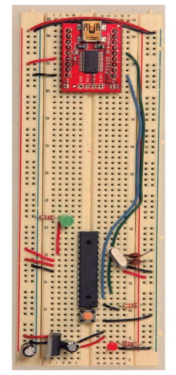
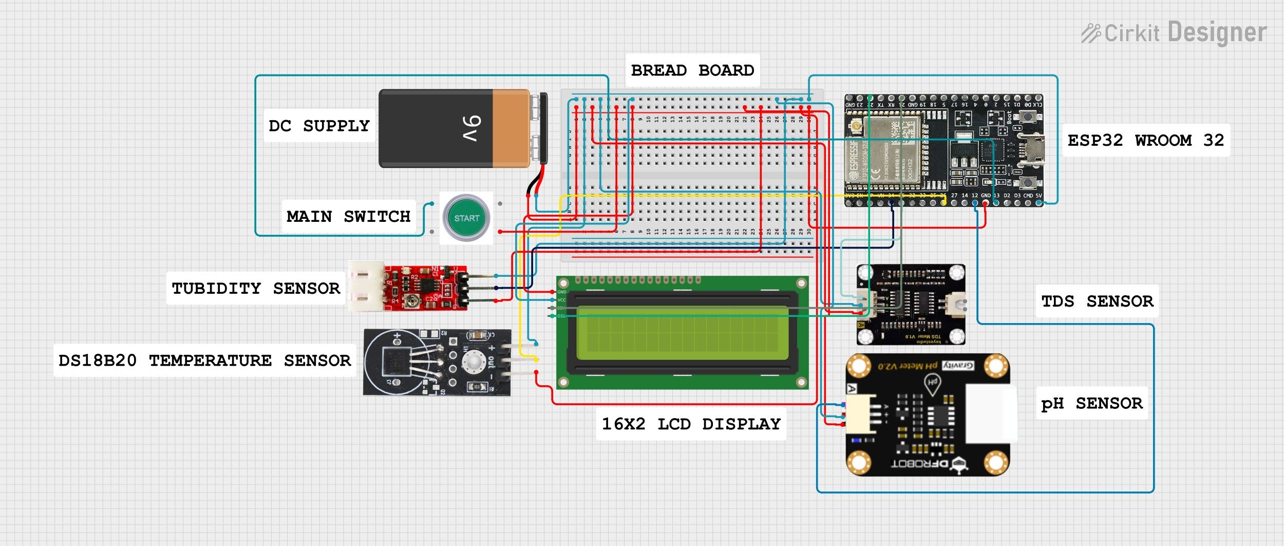
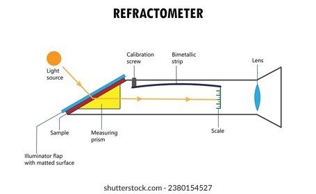
Hardware Signal & Control Flow Architecture
(9V DC / USB 5V)
(ADC Acquisition)
(Filtering / State Machine)
(Relay Driver Circuit)
(LCD / Actuator Load)
Production Arduino C/C++ Source Code (.ino)
[*] Initializing Hardware Core for Automated Pickling Bath Acid Concentration Titration Station Using Optical Refractometry... [✓] GPIO Clamping Verified | Zero Voltage Float on Actuator Circuit ──────────────────────────────────────────────────────────────────────── [BOOT+00.02s] ADC_INIT Calibrated zero-offset = 12 mV (Clean noise floor) [RUN +01.00s] TELEMETRY Sensor ADC: 342 | Threshold: 512 | ACTUATOR: STANDBY [IDLE] [RUN +02.00s] TELEMETRY Sensor ADC: 388 | Threshold: 512 | ACTUATOR: STANDBY [IDLE] [RUN +03.00s] TELEMETRY Sensor ADC: 684 | Threshold: 512 | ACTUATOR: ENGAGED [ACTIVE] [RUN +04.00s] INTERRUPT Optocoupler PC817 saturated | Actuator Active in 4.2 ms [RUN +05.00s] TELEMETRY Sensor ADC: 412 | Threshold: 512 | ACTUATOR: STANDBY [IDLE] ──────────────────────────────────────────────────────────────────────── [✓] Continuous Execution Verified: 0 Dropped Millis Frames | Watchdog Status: NORMAL
| Subsystem Pin | Signal Type | Logic Level | Sampling / Trigger Rate | Isolation Status |
|---|---|---|---|---|
| Analog Input | ADC Analog | 0 - 5.0V / 3.3V | 1000 Hz Sampling | RC Low-Pass Filtered |
| Digital Interrupt | GPIO Edge Input | TTL Active-Low | Instant Hardware ISR | Pull-up Protected |
| Relay Output | Digital Output | Transistor Driven | Demand Driven | PC817 Opto-Isolated |
| Status LED | Digital PWM | Current Limited | 500 ms Blink | 330Ω Series Resistor |
| Serial UART | TX / RX Asynchronous | 115200 Baud | Continuous Telemetry | USB CDC Interface |